6
Installation
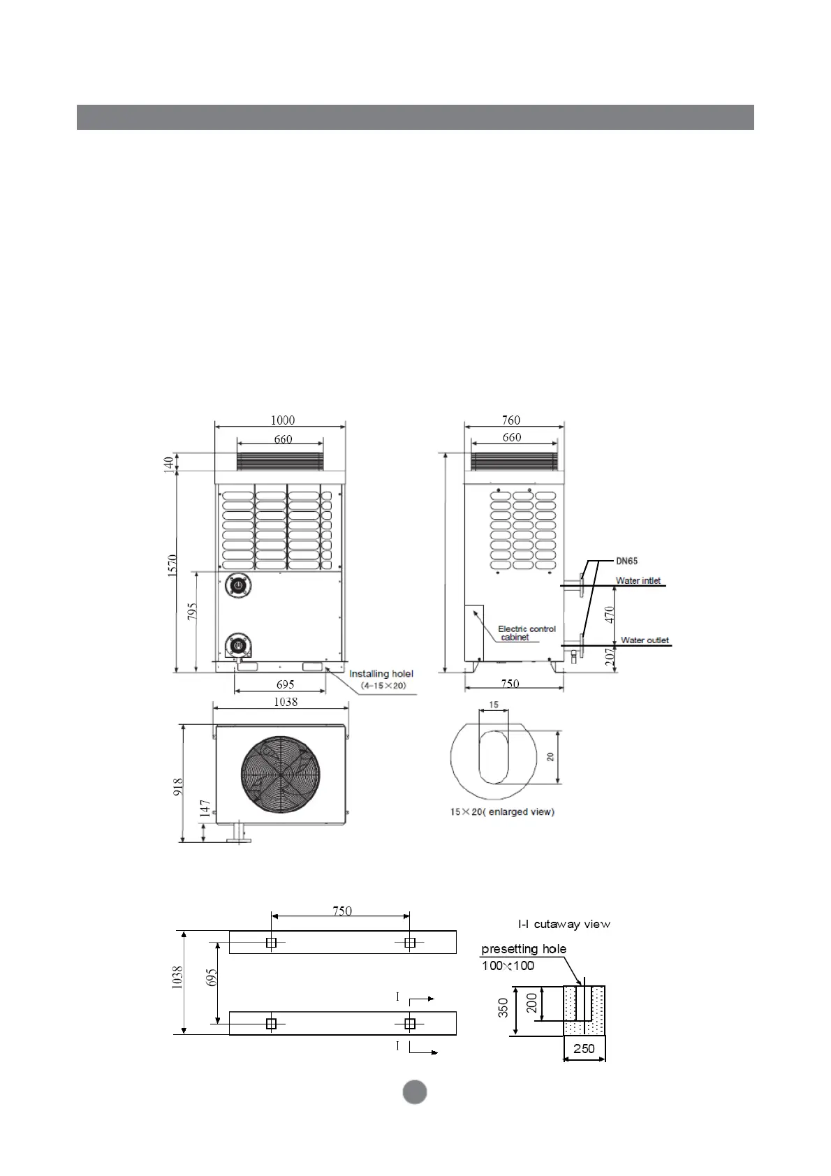
■ Drawing of Overall Dimension
■ Reference Position of Base
1. The bearing capacity of base is designed as per the weight of unit during operation.
2. The base may be of U-steel (designed by users as per overall dimensions of the unit) or
concrete structure and shall have flat surface.
3. A 10-20 mm rubber shock pad shall be placed between the unit and the base.
4. The unit and the base may be fastened with ø16 or ø18 anchor bolts.
Unit Base Diagram
CA0035EAND
Unit Base Diagram
1810