This document is a service manual for GE Appliances Connect Series Split Heat Pumps, providing comprehensive information for professional operators regarding installation, control, troubleshooting, and maintenance.
Function Description
The GE Appliances Connect Series Split Heat Pumps are designed to provide both cooling and heating functionalities for residential or commercial spaces. These systems consist of an outdoor unit (ODU) and an indoor unit (IDU), working together to transfer heat. In cooling mode, the system extracts heat from the indoor air and releases it outdoors, while in heating mode, it absorbs heat from the outdoor air and transfers it indoors. The system utilizes R-410A refrigerant and incorporates an inverter compressor for efficient operation.
Important Technical Specifications
The manual details specifications for various outdoor and indoor unit models, categorized by their cooling/heating capacities.
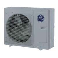
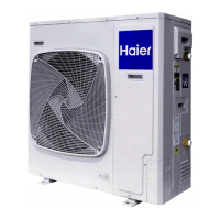
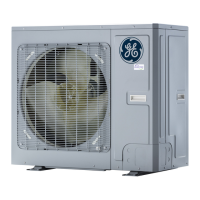
Outdoor Units (AUH2436ZGDA, AUH4860ZGDA):
- Power Supply: 208/230V-1Ph-60Hz for all models.
- Circuit Breaker Capacity: 35A for AUH2436ZGDA, 45A for AUH4860ZGDA.
- Cooling Capacity: Ranges from 24,000 to 54,000 Btu/hr.
- SEER: 17-20.
- EER: 10.5-12.5.
- Cooling Operating Range: 5~129°F (-15~54°C).
- Heating Capacity: Ranges from 24,000 to 54,000 Btu/hr.
- HSPF: 10-10.5.
- Heating Operating Range: -22~75°F (-30-24°C).
- Refrigerant Type: R410A.
- Liquid O.D. in.: 3/8.
- Suction O.D. in.: 3/4.
- Piping Connection: FLARE (for AUH2436ZGDA, AUH4860ZGDA) or BRAZE (for UUY(--)ZGDAB models).
- Factory Charge: 9.26 lbs (4.2 kg) for AUH2436ZGDA, 13.78 lbs (6.25 kg) for AUH4860ZGDA.
- Maximum Line Length: 164 ft (50 m) for AUH2436ZGDA, 98 ft (30 m) for AUH4860ZGDA (FLARE models); 164 ft (50 m) for BRAZE models.
- Maximum Height: 50 ft (15 m) for all models.
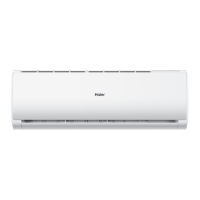
Indoor Units (UUY24ZGDAA, UUY36ZGDAA, UUY48ZGDAA, UUY60ZGDAA, UUY24ZGDAB, UUY36ZGDAB, UUY48ZGDAB, UUY60ZGDAB):
- Cooling/Heating Capacity: Ranges from 24,000 to 54,000 Btu/hr.
- Power Supply: 208/230V-1Ph-60Hz for all models.
- Fuse Capacity: 3.15A or 3.5A.
- Circuit Breaker Capacity: 15A.
- Electric Backup Heat Kits: Available in 5kW, 8kW, 10kW, 15kW, and 20kW options, with corresponding UPCs and breaker sizes (30A, 45A, 60A).
- Airflow CFM: Ranges from 940 to 1600 CFM.
- Indoor Sound Level: 47-51 dB.
- Metering Device: TXV.
- Control Voltage: 24VAC.
- Maximum Static Pressure W.C.: 0.05-1.0.
- Dimensions (H x W x D): 48 1/4 x 21 1/4 x 21 1/4 in. (1226 x 540 x 540 mm) for 24K/36K models; 57 x 24 3/4 x 21 1/4 in. (1448 x 630 × 540 mm) for 48K/60K models.
- Weight Net/Gross: 156.5/169.8 lbs (71/77 kg) for 24K/36K models; 202.8/218.3 lbs (92/99 kg) for 48K/60K models.
Usage Features
The Connect Series Split Heat Pumps offer various control modes and functions to optimize performance and user comfort:
- Operation Modes: Cooling and Heating modes are detailed with flowcharts illustrating the sequence of operations, including compressor start/stop conditions, indoor fan operation, oil return, and temperature point shutdowns.
- Compressor Control: Features a time delay to prevent short-cycling and protect the compressor.
- EXV Control: The electric expansion valve resets upon startup and opens to a predetermined step before operating in cooling or heating mode.
- Outdoor Fan Control: Outdoor fans can operate at various speeds (level 1 to 10) to achieve cooling at low temperatures and heating at high temperatures. The fan does not run in indoor-fan-only mode.
- 4-way Valve Control: Energized in heat mode (after a delay) and de-energized during cooling and defrost. It remains energized after the unit stops in heating mode to prevent inadvertent shifts to cooling.
- Defrosting Control: Initiates when the outdoor coil temperature drops below a calculated value. The 4-way valve switches to cooling, the outdoor fan stops, and the indoor fan continues. It terminates when the outdoor coil reaches a calculated defrost termination value, switching back to heating.
- Oil Return Control: Activates if the compressor runs at low frequency for an extended period, lasting about 5 minutes.
- Protection Controls:
- High Pressure Protection (E1 error): Shuts down the compressor if the high-pressure switch opens continuously. Requires power reset if it locks out.
- Low Pressure Protection (E3 error): Shuts down the compressor if the low-pressure switch opens. Automatically restarts after a delay, but locks out and requires power reset if it reoccurs.
- High Temperature Prevention: Reduces outdoor fan speed in heating mode if indoor coil temperature rises too high.
- Discharge High Temperature Protection (E4 error): Shuts down the system if the discharge temperature sensor detects high temperatures. Locks out if it reoccurs within a certain period.
- Capacity Selection: Configurable via DIP switch SA2-1 on the outdoor unit main control board.
- Defrost Mode Selection: Configurable via DIP switch SA2-2 on the outdoor unit main control board, offering Standard Defrost (default) and Strong Defrost for ultra-low temperatures.
- Operating Mode Selection: Configurable via DIP switches SA2-3 & SA2-4 on the outdoor unit main control board, offering Standard Mode (default), Strong Mode (increased output capacity), and Energy Saving Mode.
- Indoor Fan Speed: Adjustable via indoor main control board DIP switches, with higher levels corresponding to higher fan speeds.
- Forced Defrost/Refrigerant Recovery/Forced Operation: Accessible via SW1 button on the outdoor unit main board for service and diagnostic purposes.
- Query Functions: Allows querying compressor frequency, discharge temperature, and fan RPM via SW1 button.
Maintenance Features
The manual provides detailed instructions for troubleshooting and replacing major components:
- Wiring Diagrams: Electrical diagrams for both outdoor and indoor units are provided for reference.
- PCB Layout and Interface Descriptions: Detailed layouts of the main control boards for both indoor and outdoor units, with descriptions of each interface.
- IPM, PFC Testing Method: Step-by-step instructions for testing the IPM and PFC modules using a multimeter, including voltage readings for normal and failed modules.
- Troubleshooting Flowcharts: Extensive flowcharts guide technicians through diagnosing and resolving various error codes (E1, E3, E4, F2, F3, F4, F6, EE, H4, H5, H6, H7, HC, Lc, P0, P5, P6, P7, P8, PA, Pc, PL, PH, PU, ee, e1, C4), covering possible causes and corrective measures.
- Failures Not Caused by Errors: Lists common operational issues that are not system errors, such as weak thermostat battery, blocked air inlets/outlets, improper temperature settings, and normal operational noises (e.g., defrosting sounds, refrigerant flow sounds).
- System Evacuation: Instructions for evacuating the system, including connecting a vacuum pump, opening valves, and verifying pressure. Emphasizes safety precautions like proper ventilation and keeping valves closed during initial steps.
- Refrigerant Charging: Detailed procedures for both pre-charging and charging while the unit is running, including connecting gauges, purging hoses, and using an electronic scale. Highlights the importance of using only specified refrigerant and performing leak tests.
- Replacement of Major Components: Comprehensive guides for replacing components in both outdoor and indoor units:
- Compressor Replacement: Includes diagnosis of compressor failure (noise, EXV/4-way valve check), checking oil quality, preparation (sealing ports, tools, nitrogen purging), disconnecting power, recovering refrigerant, and detailed steps for removal and installation.
- Compressor Drive Module Replacement: Instructions for verifying power isolation, measuring DC bus voltage, removing wires and screws, applying silica gel, and installing the new board.
- Front Panel Removal (Outdoor Unit): Step-by-step guide for removing and installing the upper cover, front side plate, front grill, and front panel.
- Compressor/Gas Liquid Separator Removal: Instructions for removing wires, brazing pipes, loosening nuts, and taking out the components.
- 4-Way Valve Removal: Steps for removing the solenoid coil, brazing and removing connection pipes, and installing the new valve.
- Fan and Motor Removal (Outdoor Unit): Guide for removing the grill, fan, and motor, and installing new components.
- Outdoor Coil Removal: Instructions for removing panels, electric box, motor support, and brazing/removing the outdoor coil.
- Electronic Expansion Valve Removal: Steps for removing the electric box, fixed block, and brazing/removing the expansion valve.
- Electric Box Disassembly and Assembly (Indoor Unit): Instructions for removing the upper panel, disconnecting wires, loosening screws, and reassembling.
- Fan Motor Disassembly and Assembly (Indoor Unit): Guide for removing the upper panel, disconnecting wires, loosening screws, and reassembling.
- Indoor Coil And Drain Pan Disassembly and Assembly: Steps for removing panels, enhanced frame, mounting plate, primary and secondary drain pans, and the coil.
- Filter Disassembly and Assembly: Instructions for removing and installing the filter screen and mounting plate.
- Exploded View and Parts Lists: Detailed diagrams and lists of parts for both outdoor and indoor units, aiding in identification and ordering of components.
- Temperature Sensor Lists: Tables providing temperature, resistance, and voltage values for 15 KΩ, 20 KΩ (pipeline), and 50 KΩ (discharge) temperature sensors, useful for diagnostics.
- Refrigerant R-410A Temperature/Pressure List: Tables correlating PSIG and kPa pressure values with corresponding temperatures for R-410A refrigerant.
- Operation Tools: A list of recommended tools for maintenance and installation tasks.