Do you have a question about the Haier GE PDT715SYN3FS and is the answer not in the manual?
Ensure grounding wires, screws, and clips are returned to their original position and properly fastened for safety.
Required 6-step process for technicians to ensure appliance safety before disassembly.
Steps to diagnose why the dishwasher will not start, checking power, door switch, and CSM.
Step-by-step instructions for removing the dishwasher door, including disconnecting the harness.
Procedure for removing the detergent module from the inner door panel.
Steps to diagnose the detergent module using Service Mode and checking resistance.
Procedure for reinstalling the sump assembly, ensuring wiring is not pinched.
Explains critical errors like No Water, Pressure Sensor, and Continuous Fill, and their display.
Steps to enter Consumer Error Mode to view current error codes and door status.
Steps to enter Service Mode from Consumer Error Mode, noting it resets the CSM.
Guidance on diagnosing main control and UI boards, including connector access and testing.
Diagnostic flowchart and steps to test the CSM and identify causes of tripping, like water leaks.
Details on the Clear Door tool for diagnosing wash zones, spray patterns, and leaks.
Step-by-step guide for using the Clear Door tool in Service Mode to observe cycle operation.
Guidance on locating and testing the motors fuse on the main control board.
Step-by-step instructions for removing the circulation pump motor assembly.
Methods for diagnosing the diverter sensor/switch using a Clear Door tool and continuity checks.
How to diagnose turbidity sensor faults and their impact on cycle operation.
Common symptoms indicating a failure to drain, including fault codes and incomplete cycles.
Diagnostic steps to identify the cause of drain failures, checking air gaps, plumbing, and pump connections.
A schematic diagram and troubleshooting steps for the heating element circuit.
| Wash Cycles | 7 |
|---|---|
| Leveling Legs | Yes |
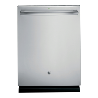
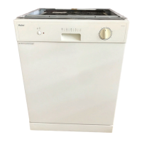
| Product Type | Dishwasher |
| Child Lock | Yes |
| Control Type | Electronic |
| Dimensions | 845 x 598 x 600 mm |
| Dispenser | Detergent, Rinse Aid |
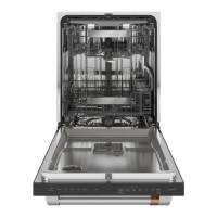
| Upper Rack Features | Adjustable |
| Lower Rack Features | Fold-Down Tines |
| Control Location | Front |
| Programs | Auto |
| Delay Start | Yes |
| Dimensions (H x W x D) | 845 x 598 x 600 mm |