This document is a technical service guide for the GE Profile 28-inch Top Load Washer, covering models PTW600BPR_DG, PTW600BSR_WS, PTW605BPR_DG, PTW605BSR_WS, PTW700BPT_DG, PTW700BST_WS, PTW705BPT_DG, PTW705BST_WS, PTW900BPT_DG, PTW900BPT_RS, PTW905BPT_DG, and PTW905BPT_RS. It provides comprehensive information for servicing and maintaining these appliances, including safety guidelines, specifications, component locator views, diagnostics, and wiring diagrams.
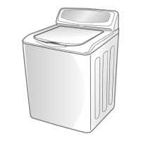
The washer's primary function is to clean laundry using various wash cycles and settings. It features a top-load design with a rear control panel. The nomenclature section explains the model number breakdown, including brand (GE Profile), configuration (Top Load Rear Control), platform (Washer), series (indicating model series and whether it's top or front load), product type (Top Load 4" Cover – Matching), color (Diamond Grey, Silver back guard, Royal Sapphire Blue), engineering revision, and model year. Serial numbers indicate the month and year of manufacture.
Technical Specifications:
The electrical specifications detail the AC and DC voltages for various components.
- AC Voltage:
- Main Board: 120 VAC to J101.
- Drain Pump: Approximately 13.2-ohms, 120 VAC.
- Mode Shifter Motor: Approximately 5.7k ohms, 120 VAC.
- Water Valves: Approximately 1.3k ohms, 120 VAC.
- Lid Lock Position Locked/Unlocked: Lid Lock Coil approximately 60- to 100-ohms between pins 2 and 3 when locked, and pins 1 and 3 when unlocked with the lid closed.
- Dosing Pump: Approximately 1.7k ohms, 120 VAC.
- Bulk Tank Level Sensor: 5 VDC.
- DC Voltage:
- User Interface (UI) Logic Board: 12 VDC / 7.5 VDC.
- Hall Sensor: 9 VDC pin 3 to pin 2.
- Accelerometer: 5 VDC.
- Turbidity Sensor: 5 VDC.
- Pressure Sensor: Digital protocol (I2C), DC output voltage cannot be measured directly.
Water Levels:
- Minimum Fill: 10.0 gallons (5.1 inches).
- Maximum Fill: 36.0 gallons (17.4 inches).
Usage Features:
The control panel varies slightly by model (900/905, 700/705, 600/605), but core functionalities are consistent.
- Power Button: Wakes up the display or puts the washer into idle mode. Does not disconnect power.
- Start/Pause Button: Initiates or pauses a cycle. The lid locks during load sensing and unlocks when paused (unless Bulky cycle is selected).
- Display and Status Lights: Shows approximate time remaining, scrolls washer status (BALANCING, DELAY, End, FILL, H2O SUPPLY, LID, SENSING, PAUSE), and indicates cycle status (Pre-wash, Delay, Fill, Soak, Wash, Rinse, Spin).
- Wash Cycles-Cycle Selector: Knob to select wash cycles. Turning the knob during a cycle stops the washer and allows for a new selection. Recommended settings are highlighted in bold.
- Sanitize with Oxi: Designed to remove 99.9% of bacteria with Oxi additive and hot water (minimum 120°F).
- Settings (Temp, Soil, Spin): Adjustable for each cycle. Longer spin times reduce dryer time/energy.
- Cycle Options:
- Deep Fill: Adds extra water. A quick press adds 3 gallons; holding for 3 seconds provides the deepest fill. Can be activated after the wash phase begins.
- Power Pre-wash (on some models): For heavily soiled loads, adds a brief wash, soak, and drain cycle.
- Tangle Control™ (on some models): Adjusts the wash cycle to prevent tangling.
- Auto Soak: Begins with agitation, soaks for a specified period (15, 30 min, 1, 2 hours), then proceeds automatically.
- Deep Rinse: Provides a deep rinse or for use with fabric softener.
- Delay Wash: Sets a delay time from 1 to 9 hours.
- Extra Rinse: For heavily soiled clothes or extra detergent/bleach.
- Smart Wash (on some models): Senses soil level and adjusts agitation/soaking times.
- Smart Rinse (on some models): Senses soil and detergent to determine if extra water is needed for thorough rinsing.
- My Cycle Settings (on some models): Stores custom Temp, Soil, Spin, Extra Rinse, Deep Fill, Auto Soak, Deep Rinse, Tangle Control, Auto, Power Clean, and Gentle Care settings for specific cycles.
- Sound (on some models): Adjusts end-of-cycle signal and system tones (high, medium, low, off).
- Control Lock: Locks controls to prevent accidental changes. Power button remains functional.
- Power Clean and Gentle Care (on some models):
- Auto: Balances performance, fabric care, and cycle time for normal/lightly soiled loads.
- Gentle Care: Reduces agitation, adds soaks for fabric wear/fading.
- Power Clean: Adds heavy agitation and soaking for deep cleaning.
- Alexa Voice Assistant (PTW905 and PTW900 Models Only): Embedded voice assistant for setting wash cycles and handling stains when connected to SmartHQ App. Voice status indicators (Yellow: Communications, Red: Muted, Purple: Do Not Disturb).
- SmartDispense™ (PTW905 and PTW900 Models Only): Automatically adds detergent based on load size. Can be manually adjusted (Less, Auto, More) or disabled.
- Consumer Help Indicator (CHI): Provides scrolling messages on the display for common issues (Spin Light Blinking, "H2O SUPPLY", "Canceled", "Lid") with simple remedies.
Maintenance Features:
The service guide details procedures for component removal, diagnosis, and reinstallation.
- Safety Requirements: GEA Factory Service Employees must use safety glasses, safety gloves, and steel toe shoes. Lockout/Tagout (LOTO) 6-step process is required before disassembly.
- Recommended Tools: Specific tools like WX05X10022 Socket, WX05X00000 3/8 x 17-3/8th Socket Extension, WX05X23817 Water Transfer Pump, WX05X10028 Torque Limiter, and WH05X25382 Strap Wrench are recommended. Standard tools include various nut drivers, sockets, wrenches, screwdrivers, putty knife, multimeter, and needle-nose pliers.
- Component Locator Views: Detailed diagrams for underside top cover (900/905, 700/705, 600/605 models), tub assembly (900/700, 905/705, 600, 605 models), backsplash assembly (900/905, 700/705, 600/605 models), and bottom view (900/905, 700/705, 600/605 models).
- Control Panel Housing / Backsplash Assembly: Removal involves hex-head screws and sliding the assembly. Includes main board, capacitor (600/605 only), lid assembly, lid strike, and lid dampers.
- Fill System:
- Water Valves: Four-solenoid valves (hot, cold, fabric softener, custom add). Resistance: 1.3k ohms, 120 VAC. Removal involves hex-head screws and disconnecting harnesses.
- Thermistor: Measures water temperature. Resistance table provided for diagnosis.
- Dosing Pump (900/905 Models Only): Dispenses detergent from the bulk tank. Resistance: 1,744-ohms. Removal involves hex-head screws and disconnecting conduit/harness.
- Bulk Tank Level Sensor: 5 VDC. Diagnosed via display status (Tank Low or Tank Empty). Removal involves hex-head screws and disconnecting harness.
- Dispenser Drawer: Holds detergent, fabric softener, PODs. Removal involves hex-head screws.
- Bleach Funnel: Directs liquid bleach. Removal involves pushing up on the bottom and tilting.
- Bulk Tank (900/905 Models Only): Stores 50 oz. of detergent. Removal involves hex-head screws and disengaging snaps.
- Lid Switch/Lock Assembly: Ensures safe operation by locking the lid. Resistance: 60- to 80-ohms (70-ohms nominal). Removal involves removing the bezel and sliding the lock assembly.
- Agitators: Two types: impeller and single stage agitator. Impeller moves clothes in the basket; agitator moves clothes back and forth. Removal involves removing the center cap and hex-head bolt.
- Basket Assembly: Consists of balance ring, side wall, and bottom. Removal involves unclasping clips, removing the hub nut (reverse threads), and lifting the basket.
- Pressure Sensor: Senses water level. Integrated into the control board (cannot be replaced separately). Diagnosed via Service Mode Test 10.
- Drain System:
- Drain Pump: Removes water from the tub. Resistance: 13.2-ohms, 120 VAC. Removal involves disconnecting power, harness, and internal drain hose.
- External Drain Hose: Directs water to house drain. Removal involves squeezing spring clamp and removing hex-head screw.
- Internal Drain Hose: Connects drain pump to external drain hose. Removal involves squeezing spring clamp and pushing locking tab.
- Drive System:
- Belt Drive (600/605 Models): Consists of belt, pulleys, drive motor, mode shifter, speed/hall sensor, and transmission.
- Drive Belt: Six ribs. Removal involves removing belt protector and walking the belt off the pulley.
- Drive/Transmission Pulleys: Drive pulley (motor side fins for cooling), Transmission pulley (gear for mode shifter). Removal involves hex-head nuts.
- Speed/Hall Sensor: Mounted on drive motor, sends pulse signal to control board. Diagnosed via Service Mode Test 14. Removal involves removing belt protector, belt, and pulleys.
- Drive Belt Motor: 1/2 horsepower, 120 VAC. Diagnosed by resistance (2.8- to 4.2-ohms between pins). Removal involves uncliping harness and removing hex-head bolts.
- Direct Drive (700/705/900/905 Models): Three-phase motor with integrated inverter on main board. Consists of rotor and stator.
- Direct Drive Motor Diagnosing: Resistance: 5.8-ohms between pins 6, 7, and 8 on J1001.
- Direct Drive Motor Removal: Unclip harness, remove rotor nut, pull up rotor, unplug speed sensor, remove fasteners, slide down speed sensor.
- Mode Shifter: Receives 120 VAC from control board, operates micro switch and clutch. Engages/disengages clutch for spin or agitation. Diagnosed via Service Mode Test 14 and resistance (5.7k ohms). Removal involves removing belt protector, belt, and pulleys.
- Platform/Transmission Assembly: Supports drive motor and planetary gears. Removal involves removing belt protector, drive motor, mode shifter, impeller/agitator, and hex-head bolts.
- Accelerometer (Direct Drive Models): Senses vibrations for out-of-balance conditions. Diagnosed via Service Mode Spin Test 14. Removal involves disconnecting connector and removing screws.
- Turbidity Sensor (Direct Drive Models): Senses dirt level to dispense detergent. Located at bottom of tub. Diagnosed via Service Mode Test 20. Removal involves disconnecting connector and removing screws.
- Main Harness Assembly: Supplies AC and DC voltage to all components. Removal involves removing backsplash, top cover, suspension, basket assembly, and hex-head screws.
- Diagnostics (Consumer Fault Mode (CFM) and Field Service Mode):
- CFM: Provides fault codes for consumers. Entry by pressing and holding Start for 10 seconds.
- Field Service Mode: For technicians. Entry by turning cycle knob seven clicks and pressing Start. Allows for running service mode tests (e.g., Main Wash Hot Water Valve, Drain Pump, Spin, Agitate, Water Quality Sensor).
- Fault Codes: A comprehensive list of fault codes (e.g., Lock Monitor, Lid Monitor, Inverter Locked Rotor Critical Fault, Mode Shift, Critical Flood Level by Pressure, Pressure Sensor Loss, Lid Switch Redundancy, Mode Shift Feedback Monitor, Temp Sensor Invalid, Dry Load Sense Timeout, Drain Pump Clearing, User Interface (UI) Timeout, Critical Lid Lock Failure, ADC Health Check Fault, Water Quality, EEPROM Communication Fault, Large OOB at High Speed, Wi-Fi Communication Fault) with descriptions and repair actions.
- Voice Module (900/905 Models Only): Diagnosed by checking harness connections.
- Control Board Connector Locator: Diagrams showing connector locations for 900/905, 700/705, and 600/605 models, with a table listing each connector and its function.
- User Interface/Wi-Fi Board: Diagrams showing connector locations for 900/905 and 700/705 models.
- Schematics / Wiring Diagrams: Detailed electrical diagrams for 900/905, 700/705, and 600/605 models.
This guide is essential for service technicians to safely and effectively diagnose, repair, and maintain the GE Profile 28-inch Top Load Washer models.