Do you have a question about the HAKO Scrubmaster B 260 R and is the answer not in the manual?
Training related to machine operation and maintenance.
Guidance for diagnosing and resolving machine issues.
Procedures for adjusting machine settings and components.
Overview of the machine's multifunction display and fault indication.
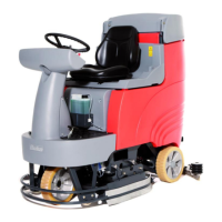
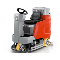
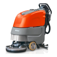
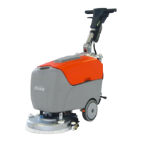
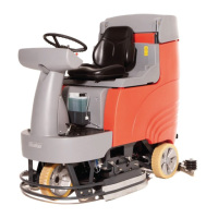
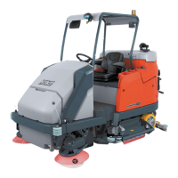
Details on available working widths, brush units, and battery types.
Explanation of order-specific manufacturing based on customer wishes.
How to access and navigate the machine's configuration menu.
Requirements and behavior of the control panel, including SD card usage.
Procedure for flashing software onto the machine control unit.
Overview of the electronic components controlling the machine functions.
How suction is switched off when the waste water tank is full.
Explanation of the fresh water tank fill level indicator and its measurement.
Functionality and behavior of the seat contact switch for machine operation.
Required components for activating the control unit after replacement.
How to download and install the Hako diagnostics software.
Steps to connect the machine to a diagnostic computer.
Procedure for flashing software onto the control unit.
How to navigate and access sub-menus within the configuration menu.
Procedure for setting the machine's time and date.
Adjusting operator and service settings via the configuration menu.
Adjusting operator-accessible settings without a code or diagnostic connector.
Adjusting service-level settings requiring a code or diagnostic connector.
Displaying and deleting the last ten errors and the error memory.
Location of the front jacking point on the machine.
Location of the rear jacking points on the machine.
How to select cleaning programmes via the configuration menu.
Table detailing settings for cleaning programs based on drive control status.
Table listing FPV program variants and their references.
SOW settings for brush and lift functions based on drive pedal position.
SOW settings for squeegee, speed, and pre-sweep functions.
How to set and adapt equipment options and working widths.
Details on different brush units and their settings for optimal functioning.
Setting the battery monitor (LDS) to the correct battery type.
Explanation of different battery types and their designations.
Information on battery charger settings and availability.
Activating the all-wheel drive variant if present in the machine.
Adjusting programmable program variants for customer-specific settings.
Importance of the SD storage medium and consequences of its absence.
Selecting the logo displayed on the start screen.
Installation and initial setup of the squeegee connection.
How to adjust squeegee inclination for optimal contact and quiet operation.
Adjusting the height of supporting rollers for optimal sealing strip contact.
Description of plate brush heads and their rotation direction.
Explanation of the three contact pressure stages for brush units.
Description of the roller brush unit and its extension with a side brush.
Functionality of the integrated position detection in the brush head lifting element.
Procedure for replacing the brush head lifting element.
How the water pump is operated and factors affecting voltage measurements.
Table listing water quantities for brush units across five stages.
Functionality of automatic water pump standstill detection for protection.
Options for scrubbing/suction and spray tools requiring activation.
Overview of drive control unit diagnostics and self-test features.
Description of the front DMC drive control unit and its connection points.
Detailed connection descriptions for the front drive control unit.
Warning codes for the front DMC control unit and their remedies.
Drive error codes for the front DMC control unit and their remedies.
Soft error codes for the front DMC control unit and their remedies.
Hard error codes for the front DMC control unit and their remedies.
More hard error codes for the front DMC control unit and their remedies.
CAN and overspeed error codes for the front DMC control unit.
Procedure for manually releasing the front brake.
Method for checking the brake function and required stopping distances.
Description of the rear DMC drive control unit and its connection points.
Detailed connection descriptions for the rear drive control unit.
Warning codes for the rear DMC control unit and their remedies.
Drive error codes for the rear DMC control unit and their remedies.
Soft error codes for the rear DMC control unit and their remedies.
Hard error codes for the rear DMC control unit and their remedies.
More hard error codes for the rear DMC control unit and their remedies.
Procedure for unlocking the rear wheel brake on X-AC drive machines.
Function and adjustment of the steering angle sensor for adapted rear axle speed.
Detailed steps for adapting the steering angle sensor to the drive motor.
Service codes and remedies for thermo switch errors in brush motors.
Service codes for blocking protection and communication interruptions.
Service codes for drive control malfunctions and motor temperature issues.
Service codes related to communication issues between control units.
Service codes for internal control unit malfunctions and USB output issues.
Interpretation of different displays shown on the dash board during machine startup.
List of available factory and field options for the machine.
How to adjust options and understand compatibility between them.
Table detailing settings for Silence Kit, Warning Signal, Dosing, and Tool options.
Table detailing settings for Pre Sweep, Working Headlight, Fleetrecorder, and Side Broom options.
Table detailing settings for Warning Beacon, BlueSpot, and Spinkle Nozzle options.
Diagram showing connections and fuses on the machine controllers.
Nominal current strengths of fuses and protected outputs for controllers.
Detailed list of connectors on the machine control unit A01.
Detailed list of connectors on the slave machine control unit A06.
Diagram showing the positions of connectors on the dash board A02.
Description of the connectors found on the dash board A02.