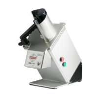
USER INSTRUCTIONS
Hallde RG-350
(GB)
CAUTION
Take great care not to injure your
hands on sharp blades and moving
parts.
Never put your hands in the feed
hopper (1:N).
Always use the pusher (1:G) when
cutting through the feed tube (1:H),
and never put your hands into the
feed tube.
The 3-phase version of the RG-350
may be installed only by an
authorized specialist.
Only an authorized specialist
should be allowed to repair the
machine and open the machine
housing.
Hold only the feeder plate handle
(1:L) when the feeder is to be
opened or closed.
The drilling sleeve (1:J) and the
stirring sleeve (1:M) must be
unscrewed clockwise by means of
the spanner (1:K).
UNPACKING
Check that all of the parts have been
delivered, that the machine operates as
intended, and that nothing has been
damaged in transit. The machine supplier
should be notified of any shortcomings within
eight days.
INSTALLATION
Connect the machine to an electric power
supply which is suitable for the machine.
The machine should be placed on a
countertop or table which is about 500 mm
high.
Locate the hanger (3:A) for the cutting tools
(2) on the wall in the vicinity of the machine
for convenient and safe use.
Check the following points without cutting
tools or ejector plate (1:D) fitted to the
machine.
Check that the machine stops when the
pusher plate (1:A) is moved up and swung
out, and that it restarts when the pusher
plate is swung in and lowered.
Check that the machine cannot be started
with the feed cylinder (1:C) removed and
with the pusher plate lowered.
Check that the machine cannot be started
with the feed cylinder (1:O) fitted but the
feed hopper (1:N) removed.
If the machine does not perform correctly,
summon a specialist for remedying the fault
before taking the machine into operation.
FITTING THE PUSHER PLATE
Fit the feed cylinder (1:C) and turn the
locking knob (1:B) clockwise as far as it will
go into locked position.
Grip the pusher plate with both hands (4:A)
and insert the shaft end (4:B) into the
mounting on the machine (4:C).
Press the pusher plate with the palm of your
right hand as far as it will go (4:D).
REMOVING THE PUSHER PLATE
Raise the pusher plate (1:A) and swing it out
to the left so that the feed cylinder (1:C) is
open.
Grip the pusher plate with both hands (4:A).
Pull up/out the pusher plate with the right
hand.
FITTING THE FEED HOPPER
Fit the feed cylinder (1:O) and turn the
locking knob (1:B) clockwise as far as it will
go into locked position.
Fit the feed hopper (4:E) to the feed cylinder
(4:F) with the feed hopper shaft (4:G)
against the mounting on the machine (4:H).
Press the feed hopper into the feed cylinder
as far as it will go.
Turn the feed hopper locking knob (4:I) anti-
clockwise as far as it will go into locked
position.
REMOVING THE FEED HOPPER
Turn the feed hopper locking knob (4:I)
clockwise as far as it will go and remove the
feed hopper.
CHOOSING THE RIGHT
CUTTING TOOLS
For dicing, the dimensions of the dicing grid
(2:G) should be equal to or larger than the
dimensions of the slicing tool (2:A, B or D).
STANDARD SLICER (2:A): Slices firm
materials. Dices in combination with type 1
dicing grid (2:G1).
DICING CUTTER (2:B): Dices in combination
with type 1 dicing grid (2:G1) from 12.5 x
12.5 mm upwards.
CRIMPING SLICER (2:C): Produces rippled
slices.
FINE CUT SLICER, 2 KNIVES (2:D2): Slices
firm and soft foods. Shreds cabbage.
FINE CUT SLICER, 1 KNIFE (2:D1): Slices
firm, soft, juicy and delicate foods. Shreds
lettuce. 4 mm chops onion in combination
with type 1 dicing grid (2:G1) 10 x 10 and
upwards. 4, 6 and 10 mm dices in
combination with type 1 dicing grid. 14 mm
and 20 mm dices in combination with type 2
dicing grid (2:G2).
JULIENNE CUTTER (2:F): Shreds and cuts
curved French fries. 2.5 x 6 mm for leaf-free
shredding of cabbage.
TYPE 1 DICING GRID (2:G1): Dices in
combination with suitable slicer. Cannot be
combined with 14 mm and 20 mm fine cut
slicer. See type 2 dicing grid below.
TYPE 2 DICING GRID (2:G2): Dices in
combination with 14 mm and 20 mm fine cut
slicer.
POTATO CHIP/FRENCH FRY GRID (2:H):
Cuts straight potato chips in combination
with 10 mm fine cut slicer.
RAW FOOD GRATER (2:K): Grates carrots,
cabbage, nuts, cheese, dry bread, etc.
FINE GRATER (2:L): Fine grates raw
potatoes, hard/dry cheese.
FITTING THE CUTTING TOOLS
Lift the pusher plate (1:A) and swing it out to
the left, or remove the feed hopper (1:N).
Turn the locking knob (1:B) anti-clockwise
and raise the feed cylinder (1:C) alternatively
(1:O).
Place the ejector plate (1:D) on the shaft
and turn/press down the ejector plate into its
coupling.
For dicing or chopping onions, first place a
suitable dicing grid in the machine and then
turn the dicing grid clockwise as far as it will
go.
For dicing, then choose a suitable standard
slicer or fine cut slicer and for chopping
onions, a fine cut slicer, and fit the slicer to
the shaft and then turn it so that the slicer
drops into its coupling.
For slicing, shredding and grating, fit instead
 Loading...