Supplied By www.heating spares.co Tel. 0161 620 6677
9
APPLIANCE INSTALLATION
4
4.1
UNPACKING THE APPLIANCE
Before installing the appliance, check that the chosen location is
suitable (section 3.2) and that the requirements for flue position
(section 3.3) and minimum clearances (Figure 1b) are satisfied.
Manual Handling Note: During the appliance
installation it will be necessary to employ caution and
assistance whilst lifting, as the appliance exceeds the
recommended weight for a one-man lift. Take care to
avoid trip hazards, slippery or wet surfaces.
4.2
PREPARING THE WALL
a) Fix the paper template in the required position (ensuring that the
necessary clearances are achieved). Ensure squareness by hanging a
plumb line.
b) Mark the position of the largest wall fixing holes.
Refer to Figures 9 & 10.
c) Mark the position of the flue outlet. For side flue installation extend
the flue centre line on to the sidewall, where the flue length exceeds 775
mm, a flue slope angle of 2.5
°
needs to be taken into account. Refer to
Figure 10. Remove the paper template.
d) Cut the hole in the wall for the air/flue duct (preferably with a core-
boring tool). The hole must be horizontal and not be less than 100 mm
in diameter. If the hole is not accessible from outside, its minimum
diameter must be sufficient to allow insertion of the wall liner (130 mm,
5 in). The wall liner is available as an optional extra and must be sealed
in position with mortar (or equivalent).
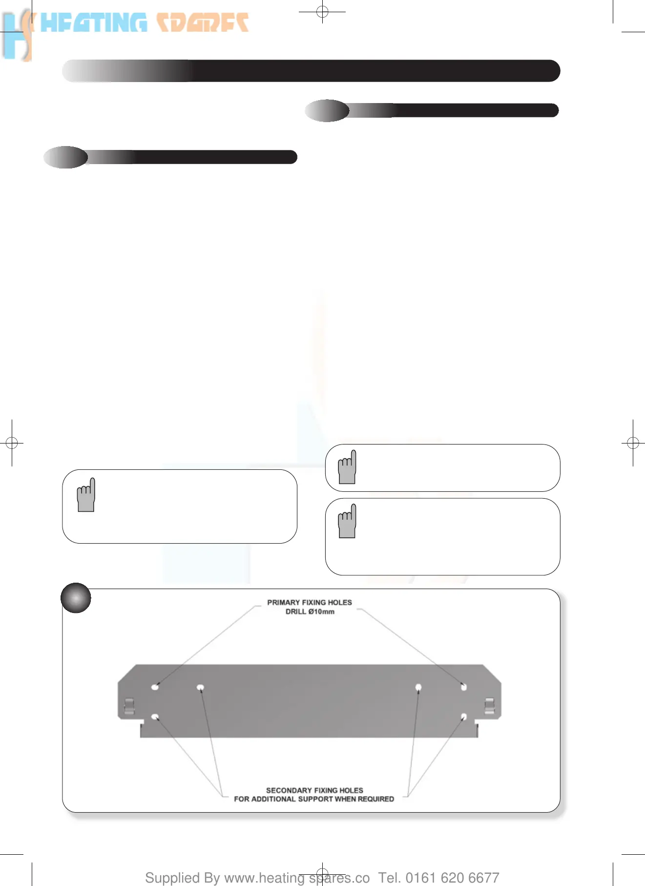
e) Drill the two largest fixing holes using a 10mm drill and insert the
blue wall plugs provided. (Further holes can then be drilled should
additional support be required for the boiler. Screws and wall plugs are
not supplied for this)
f) Hang the wall mounting plate using the two large fixing screws
supplied, ensuring that it is level. Refer to Figure 10.
g) Fit any additional fixing screws into wall plugs and tighten all
screws.
As standard the pipe work may only be routed
from below.
Note: Once the appliance has been installed and
all Gas and Water connections have been made,
the case base MUST be fitted on the underside of
the boiler. Instructions are provided on the base
panel.
WALL MOUNTING PLATE
15
The appliance is supplied in one box. Flue kits are provided
separately, the various flue kits available as described in sections
2.5 - 2.7. If the appliance is to be installed without access to an
external wall, a wall liner kit is also required.
Unpack the boxes and check the contents:
Complete appliance
Paper wall mounting template
Wall mounting plate
Case Base
Installation and Servicing Instruction
User’s Instructions
Hardware pack containing:
6 x 65 mm wood screws – 2 off
Blue wall plugs – 2 off
15mm flanged nuts – 3 off
15mm Male flanged nut – 1 off
15mm Olives – 4 off
22mm flanged nuts – 2 off
22mm Olives – 2 off
751094 ACE HE INST MANUAL:751094 ACE HE 28/9/10 09:45 Page 17