Supplied By www.heating spares.co Tel. 0161 620 6677
The design of the appliance is such that the combustion chamber
insulation should not require replacement unless mechanically
damaged. It is recommended that to prevent dust, the insulation is
dampened prior to removal, and that a protective mask is worn
when changing or handling the insulation material.
Refer to Figure 40
a) Ensure supply voltage is isolated, and that the gas supply is
isolated.
b) Remove the gas control valve, fan & burner assembly; refer to
section 6.2.
c) Remove the electrodes; refer to section 9.1.
d) Remove the burner: refer to section 9.5.
e) Replace the combustion chamber front insulation.
f) Re-assemble the burner and electrodes, using new gaskets.
g) Check the position of the electrodes: refer to section 6.4.
h) Re-assemble in reverse order; ensure that all joints and seals are
correctly re-fitted.
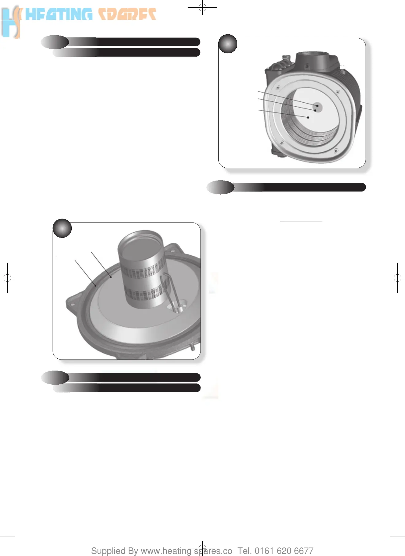
FRONT INSULATION
9.6
COMBUSTION CHAMBER
40
Refer to Figure 41
a) Ensure supply voltage is isolated, and that the gas supply is
isolated.
b) Remove the gas control valve, fan & burner assembly; refer to
section 6.2.
c) Use an Allen key to undo the central screw holding the rear
insulation in place.
d) Remove old insulation and fit replacement, ensuring locating
washer is in front.
e) Re-assemble in reverse order; ensure that all joints and seals are
correctly re-fitted.
REAR INSULATION
9.7
COMBUSTION CHAMBER
9.8
HEAT EXCHANGER
If thermal fuse has activated (open circuit and error code
‘
5
’) the heat exchanger must be replaced.
Refer to Figures 15, & 42
41
a) Ensure supply voltage is isolated, and that the gas supply is
isolated.
b) Remove the gas control valve, fan & burner assembly; refer to
section 6.2.
c) Disconnect the electrical leads to the flue sensor, flow sensor,
return sensor and thermal fuse.
d) Drain down the appliance; refer to section 9.23.
e) Disconnect the flue system from the appliance, 4 screws, and lift
up to disengage the flue from the flue adaptor; refer to Figure 15.
f) Remove the retaining clip from the heat exchanger flow outlet,
and undo the nut connecting the flow pipe to the plate-to-plate heat
exchanger.
g) Rotate the flow pipe anticlockwise and gently pull down to
disengage the flow pipe from the heat exchanger.
h) Remove the retaining clip from the heat exchanger return inlet,
and undo the nut connecting the return pipe to the hydroblock
adaptor fitting.
i) Rotate the return pipe clockwise and gently pull down to
disengage the return pipe from the heat exchanger.
j) Disconnect the condensate drainpipe from the condensate drain
adaptor; refer to section 6.6.
k) Undo the nut holding the manual air vent to the expansion vessel
and disengage the vent from the heat exchanger by removing the
clip and pulling upwards through the grommet at the top.
l) Remove the 2 screws retaining the spark generator to the right
hand saddle bracket.
m) Remove the 2 screws retaining the expansion vessel upper
bracket to the left hand saddle bracket.
n) Remove the 4 screws that retain both the left and right saddle
brackets to the heat exchanger mounting brackets; refer to Figure 44.
o) Remove the saddle brackets and slide the heat exchanger
forwards and out.
FRONT INSULATION
OUTER SEAL
REAR
INSULATION
SCREW
WASHER
34
751094 ACE HE INST MANUAL:751094 ACE HE 28/9/10 09:46 Page 36