14
18
DETERMINING THE POSITION OF THE
AIR/FLUE DUCT HOLE
19
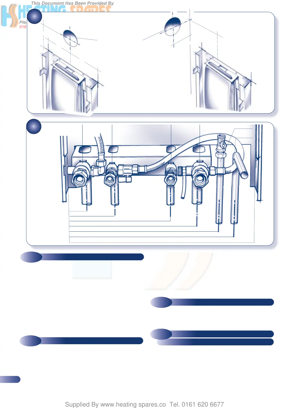
a) Connect the central heating system to the boiler flow and
return using the connections shown in Fig. 19.
b) Connect the mains water supply and outlet to the appropriate
connections as shown in Fig. 19.
c) Complete the domestic hot water and central heating system
pipework so that the system can be commissioned before the
boiler is fitted.
d) Commission the central heating system as described in section
5.1, then proceed to section 4.4.
a) Using a
1
/
2
” x 15mm fitting connect the gas supply to the gas
service cock using a suitable jointing compound.
Remove and discard the protective plastic caps on the
appliance rear connections-ensure the nylon seals on the
service connections on the MBC are in place and undamaged.
a) Lift the boiler into position. Position the top of the boiler
approximately 10mm above the top of the MBC and use the
tabs on the MBC to locate the boiler in a horizontal direction,
4.3
SERVICE CONNECTIONS
4.4
FITTING THE BOILER
4.5
GAS CONNECTION
then carefully lower the boiler ensuring locating tabs are
securely engaged (see Fig. 17).
b) Locate and tighten the water connection unions. (Seals are
pre-fitted).
c) Pass the pressure gauge through from the MBC to the plastic
boiler fascia and push into position (See Fig.33).
•
•
•
•
•
225mm
225mm
95mm
18(b) SIDE FLUE
95mm
200mm
•
•
•
•
18(a) REAR FLUE
POSITION OF DUCT HOLE
•
CENTRAL
HEATING
RETURN
•
MAINS WATER
IN
•
DOMESTIC
HOT WATER
OUT
•
CENTRAL
HEATING FLOW
•
•
•
•
•
•
•
•
•
•
GAS SUPPLY
PRESSURE
RELIEF
45mm
•
110mm
•
243mm
•
308mm
•
355mm
•
371mm
•
450mm
SERVICE
CONNECTIONS
•
POSITION
OF MBC
•
POSITION
OF MBC
SERVICE
CONNECTION
PIPES NOT
SUPPLIED
a) Connect a suitable discharge pipe to the pressure relief valve
tube. The pipe should be a minimum diameter of 15mm
copper and should avoid any sharp corners or upward pipe
runs where water may be retained. The discharge pipe must
terminate in an area where any discharge will not cause a
hazard but will be noticed.
4.6
PRESSURE RELIEF VALVE
PIPE CONNECTION