4.7.4
INSTALLING THE AIR/FLUE DUCT
FROM OUTSIDE THE BUILDING
28
ELECTRICAL CONNECTIONS
27
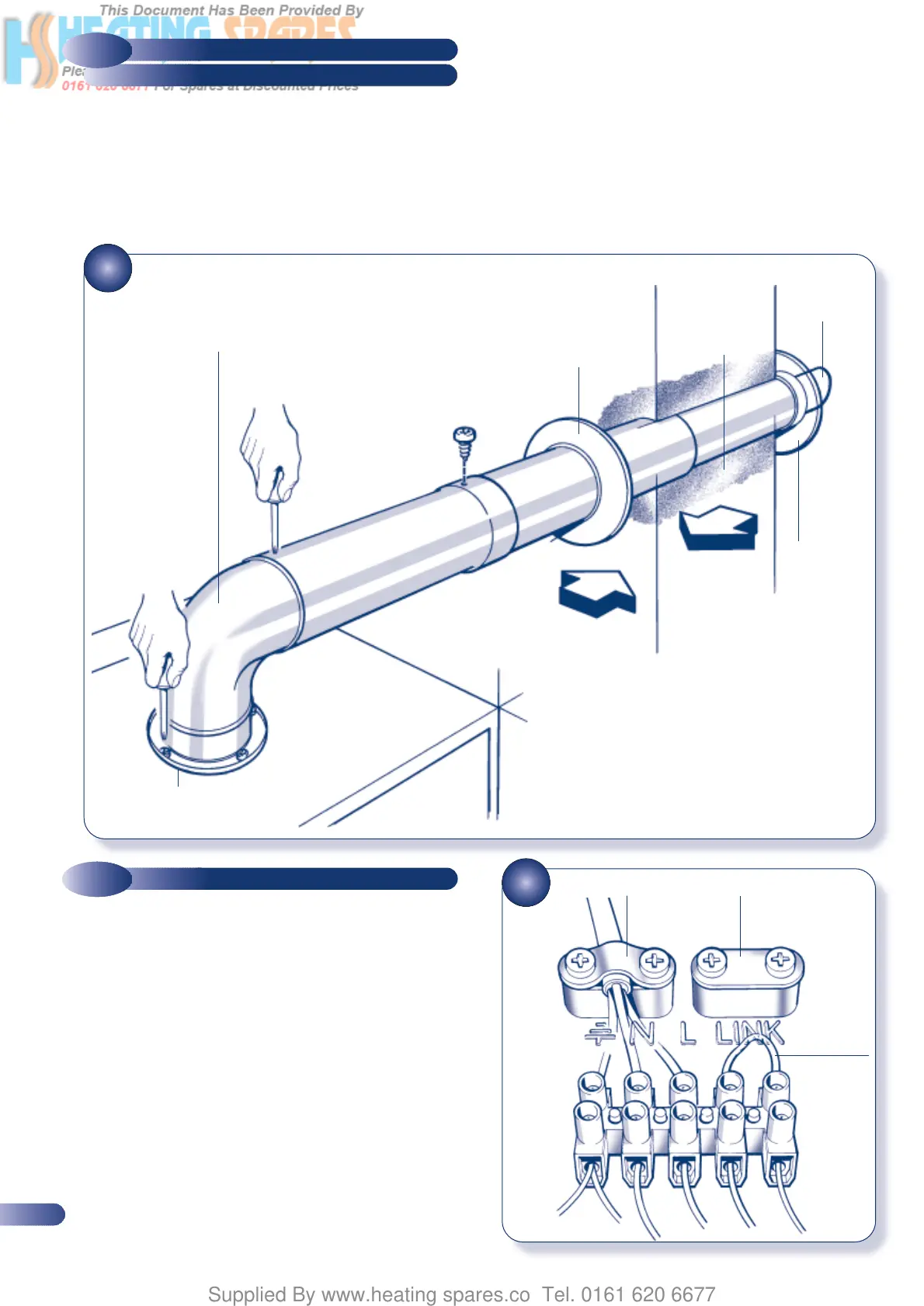
INSTALLING THE FLUE SYSTEM FROM OUTSIDE THE BUILDING
4.8
WIRING INSTRUCTIONS
(Flue hole diameter 100mm - wall liner not necessary)
a) Secure the flue elbow with seal to the appliance using 4 screws.
b) Fit external wall sealing ring over flue and then from outside the
building, push the flue system through the wall taking care to
ensure that the terminal is the correct way around.
c) Fit the internal wall sealing ring over the inside end of the flue,
then fit the air duct to the elbow, drill and secure with the two
screws.
d) Pull the flue system towards the boiler to seat the external
sealing ring against the outside wall and secure the air duct to
the elbow using the two screws provided.
e) Finally use the internal sealing ring to make good the internal
hole. Check that the external wall sealing ring is correctly
located, on the outside wall from outside the building.
Figure 27 shows a view of the flue system, correctly installed.
Connect the electricity supply and any external controls (using
suitable mains cable) as described below:
a) Unscrew the two screws securing the control panel in position
and pivot the control box downwards.
b) Wire the cable(s) into the appropriate connections in the
terminal block (Fig. 28). For further details regarding the
connection of external controls, consult the wiring diagrams in
section 7. Any external controls fitted must be rated at 230V
and have volt-free contacts.
d) Route the cable(s) through the cable clamp, secure the clamp,
and thread the cable through the MBC at the rear of the
appliance.
e) Rotate and secure the control panel in position.
NOTE: Assuming that the appliance is to be commissioned immediately
after installation it is not necessary to fit the casing panels at this stage.
•
•
•
•
•
4 REFIT AND SECURE
ELBOW TO AIR DUCT,
THEN TO APPLIANCE
1 FIT ELBOW
(AFTER SETTING CORRECT
LENGTH AND ALIGNMENT)
3 SLIDE INTERNAL
WALL SEALING RING
OVER AIRDUCT. PUSH
AGAINST THE WALL TO
FORM A GOOD SEAL
2 INSERT FLUE
LENGTHS FROM
OUTSIDE THE
ROOM. ENSURE
EXTERNAL WALL
SEALING RING
FORMS A GOOD
SEAL
•
EXTERNAL
WALL
SEALING
RING
TOP
100mm
Dia. HOLE
INTERNAL WALL
SEALING RING
•
MAINS
CONNECTIONS
•
CLAMP FOR
EXTERNAL
CONTROLS CABLE
•
LEAVE THE
LINK
BETWEEN
THESE
TERMINALS
IF NO
EXTERNAL
CONTROLS
ARE FITTED
INTERNAL WIRING
•
FIBRE SEAL FITTED
18