30
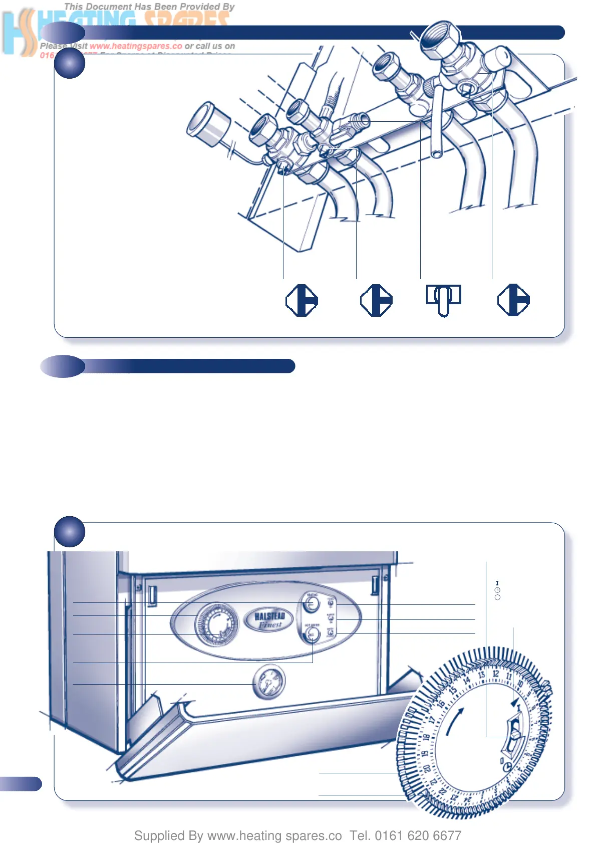
VALVE POSITIONS FOR
NORMAL OPERATION
5.3
COMMISSIONING THE APPLIANCE
31
FASCIA PANEL AND CONTROLS
5.2
COMMISSIONING THE CENTRAL HEATING CIRCUIT
a) Loosen the screw and connect a manometer to the burner
pressure test point on the gas valve (Fig. 36).
b) Ensure that the clock override switch on the fascia panel
(Fig. 31) is set to the ‘OFF’ position (hot water only) then turn
the hot water control (Fig. 31) to maximum (fully clockwise).
Turn on the electrical supply. The pump and fan will operate
for 10 seconds whilst the controls check the operation of the
air pressure switch, the water flow switch, and the overheat
thermostat. (If any of these are not operating correctly the
safety lock-out LED will be illuminated refer to section 8.2)
c) Fully open any DHW tap and the ignition sequence will
commence. If the burner fails to light, three ignition attempts
are completed before ignition lock-out occurs. In the event of
ignition lock-out the safety lock-out LED will flash. To re-set the
appliance and initiate a further series of ignition attempts it is
necessary to turn off the power supply for a period of ten seconds.
(or turn off the DHW demand for 10 seconds).
d) Allow the boiler to run for at least 10 minutes and check that
the burner pressure is as stated on the data badge ±10%.
The DHW burner pressure is factory set and should not
require adjusting. If the burner pressure is low, check that the
appliance has not started to modulate (This will occur if the
•
POWER ON LED (GREEN)
•
CENTRAL
HEATING
CONTROL
•
CLOCK
•
OVERRIDE
SWITCH
•
PRESSURE
GAUGE
•
DOMESTIC
HOT WATER
CONTROL
•
BURNER ON LED (AMBER)
•
SAFETY LOCKOUT LED (RED)
•
ARROW
INDICATES
CURRENT TIME
•
TABS OUT
= ON PERIOD
•
TABS IN
= OFF PERIOD
•
CLOCK OVERRIDE
SWITCH (Heating only)
= Continuous ON
= Timed
= OFF
1 Check that the boiler connections are tight and open the
valves by turning them to the position shown. If it is
necessary to top up the pressure, connect the hose and
repeat the procedure in section 5.1
2 Check the operation of the pressure relief valve (Fig. 33) by
rotating the plastic head anticlockwise 1/4 of a turn and checking
that water is discharged. Ensure that the valve seats correctly and
does not leak. If the valve leaks or is stuck closed, replace it.
3 Remove the pump end cap and using a screwdriver rotate
the rotor, replace cap. Prior to firing up the boiler to set gas
rates, the Central Heating and Boiler system should be checked for
circulation by running the boiler and pump with gas turned off, to
ensure no air locks occur.
CENTRAL
HEATING
RETURN
COLD
WATER IN
FILLING
LOOP VALVE
CENTRAL
HEATING
FLOW
OPEN
OPEN
CLOSED
OPEN
•
•
•
•
20