4
5
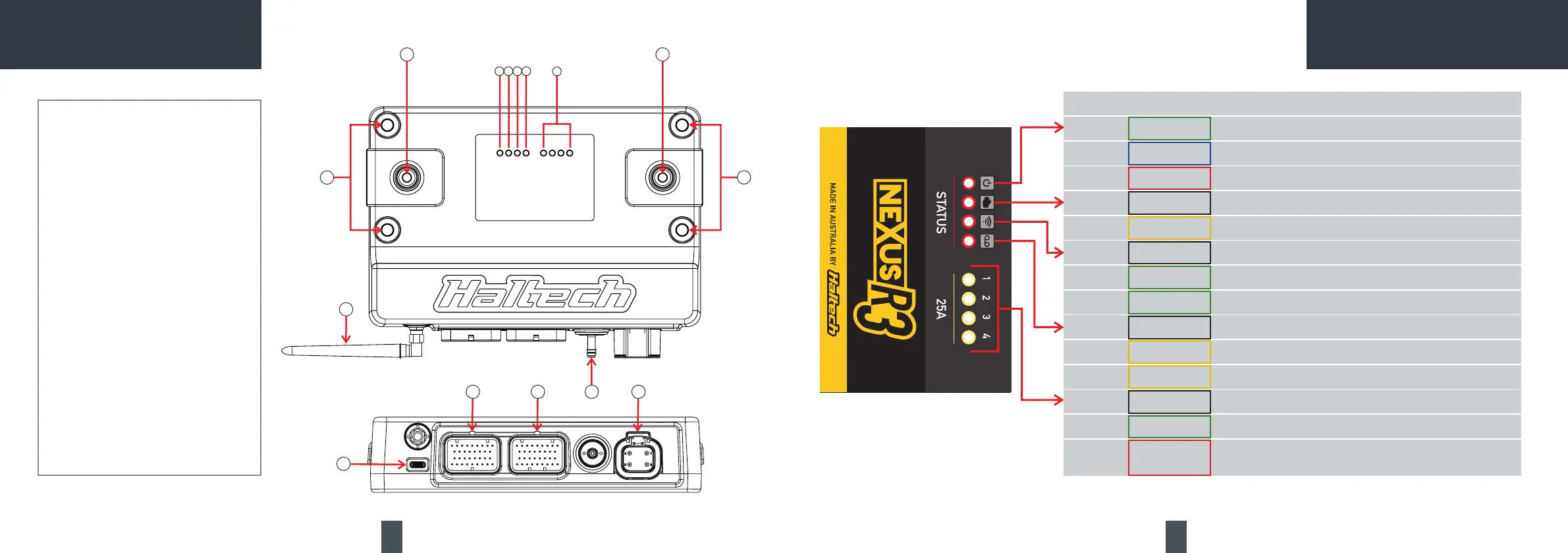
1 Power LED
2 DTC LED
3 Wi-Fi LED
4 Datalog LED
5 25A HCO LEDs
6 Battery Negative Stud
7 Battery Positive Stud
8 Wi-Fi Antenna (RP-SMA)
9 Onboard MAP sensor (4 BAR)
10 USB-C Port (Comms)
11 Connector A (AMP 34 pin Keyway 1)
12 Connector C (AMP 34 pin Keyway 2)
13 Connector E (DTP 4 pin)
14 Mounting Holes
8
12
3
4
5
6
7
14
14
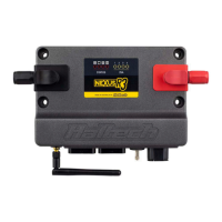
NEXUS R3 OVERVIEW NEXUS R3 LED BEHAVIOUR
LED COLOUR CONDITION
Power Green Normal operation (on main power or low power mode)
Blue Connecttounitandinstallrmware
Red Hardware fault
DTC None DTCs not present
Yellow A DTC is present (of any kind, past/present/not severe/severe)
WiFi None Wi-Fi is disabled
Green solid Wi-Fi is enabled
Green ashing Wi-Fi is enabled and connected to NSP
Datalog None Unit is not logging
Yellow ashing Unit is logging, unit is not looping or not full
Yellow Unit is logging, unit is looping or full
HCO (25A) None Channel is off
Green Channel is on - duty cycle is >0% and operating correctly
Red Channel is not allowed to be driven. Usually caused by (but not limited to)
an overcurrent this drive cycle