Document #101-0079 7 11/30/17
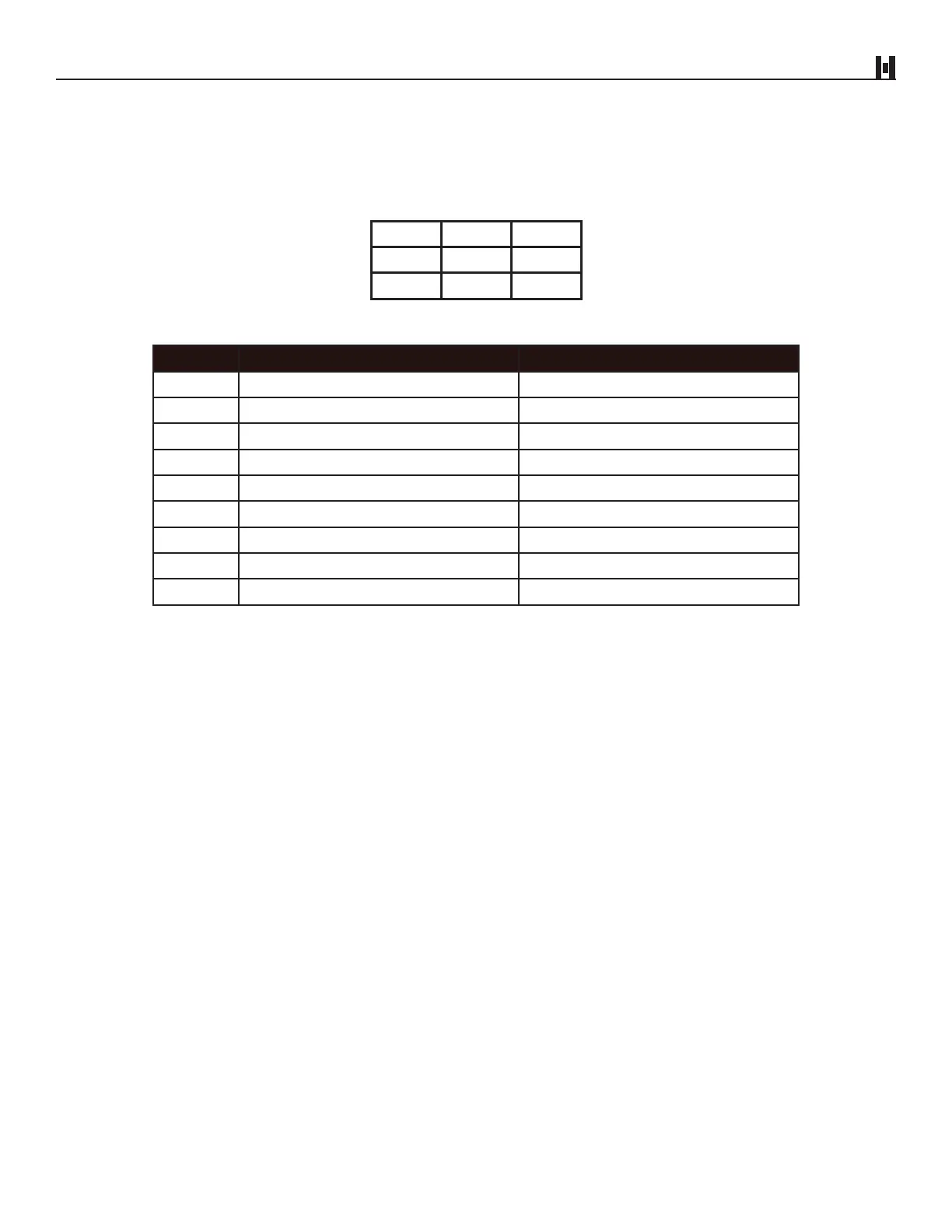
The electrical connections are made via a 9-pin connector located on the rear panel of the unit. The following
diagram and chart have been included for custom installation.
9-PIN CONNECTOR
EXTERNAL VIEW
3 2 1
6 5 4
9 8 7
WIRE VIEW
PIN # COLOR NAME
1 Blue Enable
2 White 120VAC Neutral
3 Brown Vend Common
4 N/A N/A
5 N/A N/A
6 Green Ground
7 White/Blue $1 Vend Contact Closure
8 White/Brown $5 Vend Contact Closure
9 Black 120VAC Hot
III. ELECTRICAL CONNECTIONS