3
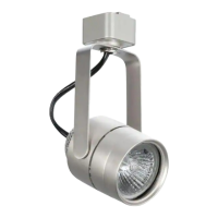
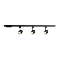
PARTS INCLUDED FOR ASSEMBLY (parts are not to scale):
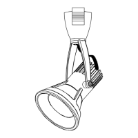
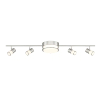
X1 Track Fixtures x1 GU10 Shielded Bulbs
INSTALLATION
1. Push the top portion of the head adapter into the slot of the track section.
2. Pull down the adapter’s locking tab.
3. Turn “Ground Indicator” tab towards the ground groove on track to align ground
tab with ground conductor.
4. Adapter can move to any position along the track section. Lighting fixture will
adjust to any position.
REMOVAL
1. Pull down the adapter’s locking tab.
2. At the same time, rotate the adapter 90 degrees and remove from track.
INSTALLING NEW BULB OR RE-LAMPING (Not provided on all models)
1. Turn the power off. Make sure that the bulb is cool before re-lamping the fixture.
2. Remove the head from the track. The track head sleeve must be pulled down the
twist 1/4 turn.
3. Twist to remove bulb from the socket, Replace with new bulb.
4. Replace the track head onto the track. Pull down the locking sleeve and reverse
the 1/4 turn.
CAUTION: Please refer to the re-lamping label located on the fixture for recommended
maximum wattage.
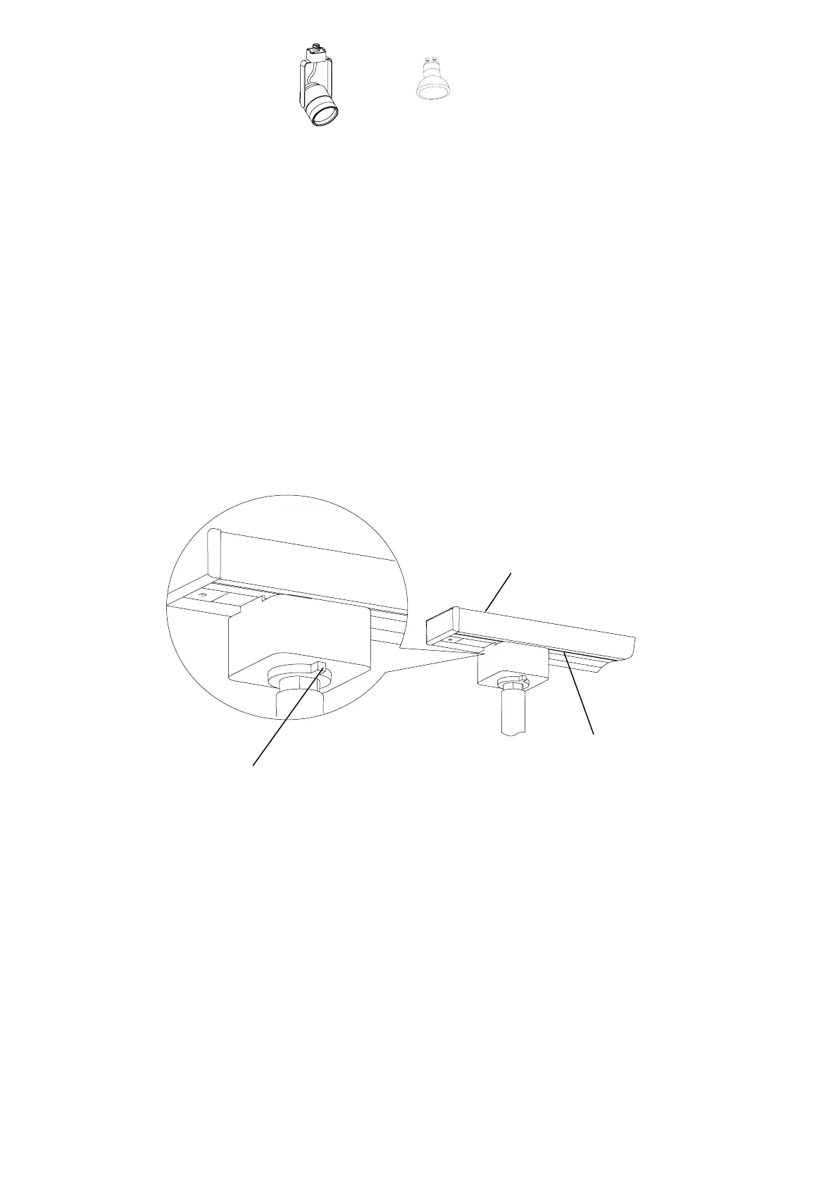
ASSEMBLY DIAGRAM:
CAUTION: Adapter is designed to lock into the track section by turning adapter in one
direction only. Turn the “ground indicator” tab towards the “ground groove” on the track
to align the ground tab with the ground conductor inside the track.
GROUND INDICATOR
TRACK (sold separately)
GROUND GROOVE