6
Installation (continued)
4
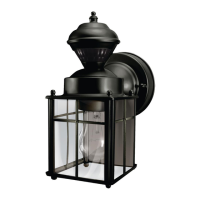
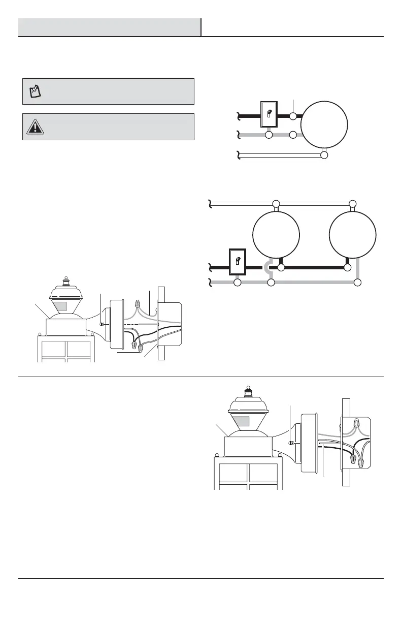
Wiring the light fixture
NOTE: This light xture can be wired to control another
standard or motion sensing light xture(s). See Wiring
Options for additional wiring methods.
CAUTION: DO NOT remove the wire connector from
the RED wire or connect the RED wire unless you want to
control other lights from this motion sensor xture.
Ƒ Route the junction box wires through the large
hole in the mounting bracket (EE) and connect
to the wires on the light xture (A).
Ƒ Using the wire connectors (BB):
Ƒ Connect all white wires together.
Ƒ Connect all black wires together.
Ƒ Recommended grounding method: Attach
a copper wire pigtail (2) (not included) to
the green ground screw on the mounting
bracket (EE).
Ƒ Connect all ground wires to the pigtail
wire (2) attached to the green ground
screw.
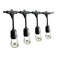
Black to black
White to white
One motion sensing light
Ground to ground
Light
Black to black
White to white
Ground to ground
Light Light
Two motion sensing lights (working independently)
5
Mounting the light fixture base
Ƒ Push the wires into the juction box.
Ƒ Slide the light xture (A) onto the large
mounting screws (DD) and tighten the
decorative xture nuts (CC) against the light (A).
Ƒ Install one medium base light bulb (60 Watt
maximum, tungsten incandescent - not
included).
Ƒ Caulk around the light xture (A) base with
silicone weather sealant.
Ƒ See the Operation section for testing and
setup.
BB
CC
CC
EE
A
A
DD
2
 Loading...