27
the chassis.
14. Replace the bulb in the socket and ret
the socket. Carefully fasten all the wires
with insulating tape or cable ties.
15. Reconnect the negative lead to the
battery.
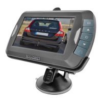
INSTALLATION OF MONITOR
IMPORTANT:
Install the monitor where it does not obstruct
the view when driving.
1. Clean the surface before mounting the
monitor.
2. Place the suction cup on a smooth surface
where the monitor can be easily seen.
3. Press the suction cup against the smooth
surface and press down the locking lever
to lock it to the surface.
FIG. 8
4. Click the monitor into the suction cup.
FIG. 9
5. Adjust the arms of the suction cup so that
the monitor is at the right angle and lock
this position by tightening the screws.
FIG. 10
6. Lead the monitor cable to the 12/24
V cigarette lighter socket, without it
interfering with driving the vehicle.
7. Put the small 12/24 VDC plug in the port
on the right side of the monitor.
8. Put the large 12/24 V plug in the cigarette
lighter socket.
9. For best functionality and secure grip the
suction cup should be mounted when:
– The surface temperature is between
21 to 38°C.
– The ambient temperature is at least
10°C.
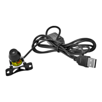
back of the reversing lights. You may need
the wiring diagram to nd the reversing
lights and suitable connection points –
contact the vehicle manufacturer.
9. After nding a suitable connection point
to the reversing light circuit, route the
cable to this point. Carefully install and
x the cable, making sure that it cannot
chafe against or fasten in any part of the
vehicle, such as the hinges for the boot.
Never route the cable on the outside of
the vehicle.
10. Two wires are connected to the reversing
lights in most vehicles. The negative wire
is usually black and the positive wire is
coloured. If in doubt, use a multimeter or
other suitable measuring instrument to
determine which wire is the positive one.
Use the multimeter in accordance with the
instructions of the instrument manufacturer.
1. Camera
2. Cable
3. Red
4. Black
5. Reversing light
6. +12/24 VDC to reversing light
7. Earth
8. Slip on terminal
FIG. 6
11. When the polarity (positive and negative
wires) has been determined, switch o
the ignition and disconnect the negative
lead from the battery.
12. Connect the red wire to the positive wire
for the reversing light with the supplied
slip on terminal. Press in the tap on the
terminal with a pair of pliers to ensure
good electrical connection.
FIG. 7
13. Connect the black wire to the negative
wire for the reversing light or earth it to