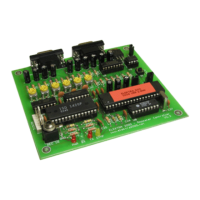
Note 1: If exposed to high levels of RF without a proper shield, it may present unstable operation.
Note 2: Use shielded cables for audio signals to avoid undesirable noises on repeater audio.
DETERMINING COR LOGIC
Locate your repeater receiver’s COR output. This line has a DC voltage that changes state when a signal
is being received. If the COR line is 0 volts and goes to a positive voltage when a signal is received it is
said to be (positive logic) or active HIGH. If the COR line is a positive voltage, and goes to 0 volts when a
signal is received it is said to be (negative logic) or active LOW. Note: 0 volts is any voltage less than
0.8VDC. A positive voltage is any voltage greater than 2.0VDC.
POSITIVE COR (+)
If you receiver has positive COR, jumper J2 should be at 1-2 position.
NEGATIVE COR (-)
If you receiver has negative COR, jumper J2 should be at 2-3 position.
Note: COR for link port works the same way using at jumper J3.
AUDIO QUALITY
The fidelity of retransmitted audio won’t depend just of the controller’s audio circuit, but from where you get the
audio from the receiver and where you inject on the transmitter
De-emphasis and Pre-emphasis
Before an FM transmitter transmits the audio on the air, the audio coming from the microphone has to pass through a
pre-emphasis circuit. This circuit boosts the audio at 6dB per octave. Pre-emphasis is needed in FM to maintain a
good signal to noise ratio. At the receiver side, a de-emphasis circuit takes the unnatural sounding pre emphasized
audio and turns it back into its original response. Pre emphasized (discriminator) audio is available directly from the
audio demodulation (discriminator) circuitry.
Plain Audio
The main idea is your repeater gets the discriminator audio from the receiver (pre emphasized at origin) and
retransmits without any modification injecting this audio at modulator’s transmitter (after pre-emphasis circuitry).
That way your repeater audio response will be more natural.
The configuration “receiver speaker output”/”transmitter microphone input” can be used, but will required some
equalization to allow a natural sound. You can modify the controller’s flat audio response using capacitors in your
audio circuits. See more details on this on page 5.

 Loading...