ITX-D255R Mini-ITX Mother Board Manual
11 / 31
2.6 Onboard Header and Connectors
Onboard headers and connectors are NOT jumpers. Do NOT place jumper caps over these headers and connectors.
Placing jumper caps over the headers and connectors will cause permanent damage of the motherboard!
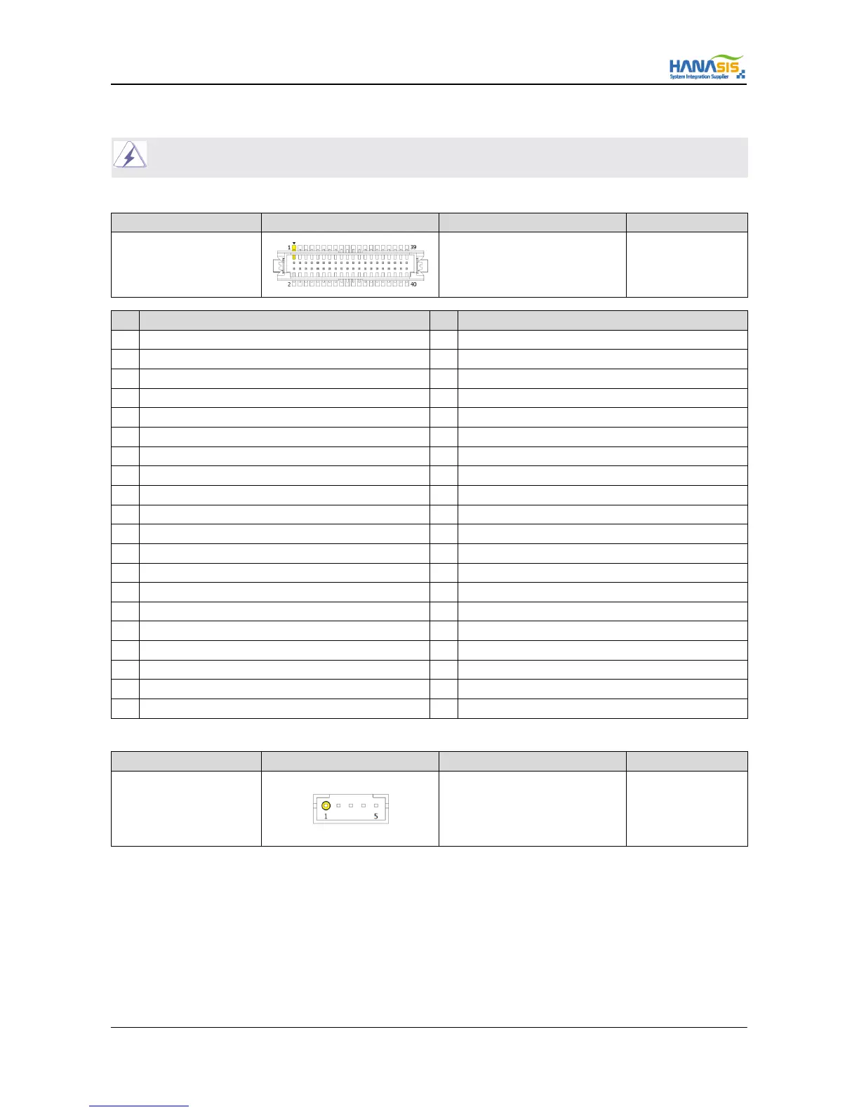
2.6.1 LVDS Connector
Connector SPEC Shape Signal Description Remark
40-Pin 1.25 Pitch Refer to below
No Signal Description No Signal Description
1 +12V 2 +12V
3 +12V 4 +12V
5 +12V 6 GND
7 VCC 3.3V 8 GND
9 LVDS Panel PWR 10 LVDS Panel PWR
11 DDC CLK 12 DDC DAT
13 Back Light Adjust 14 LVDS Power Enable
15 Back Light Enable 16 GND
17 LVDS#1 D0 (-) 18 LVDS#1 D0 (+)
19 LVDS#1 D1 (-) 20 LVDS#1 D1 (+)
21 LVDS#1 D2 (-) 22 LVDS#1 D2 (+)
23 LVDS#1 CLK (-) 24 LVDS#1 CLK (+)
25 LVDS#1 D3 (-) 26 LVDS#1 D3 (+)
27 GND 28 GND
29 LVDS#2 D0 (-) 30 LVDS#2 D0 (+)
31 LVDS#2 D1 (-) 32 LVDS#2 D1 (+)
33 LVDS#2 D2 (-) 34 LVDS#2 D2 (+)
35 LVDS#2 CLK (-) 36 LVDS#2 CLK (+)
37 LVDS#2 D3 (-) 38 LVDS#2 D3 (+)
39 GND (LVDS Detection) 40 GND
2.6.2 Inverter / Back Light Connector (IVCN)
Connector SPEC Shape Signal Description Remark
5-Pin 2.0 Pitch
1 : +12V
2 : GND
3 : Back Light Enable
4 : Back Light Adjust
5 : +5V