ITX-D255R Mini-ITX Mother Board Manual
13 / 31
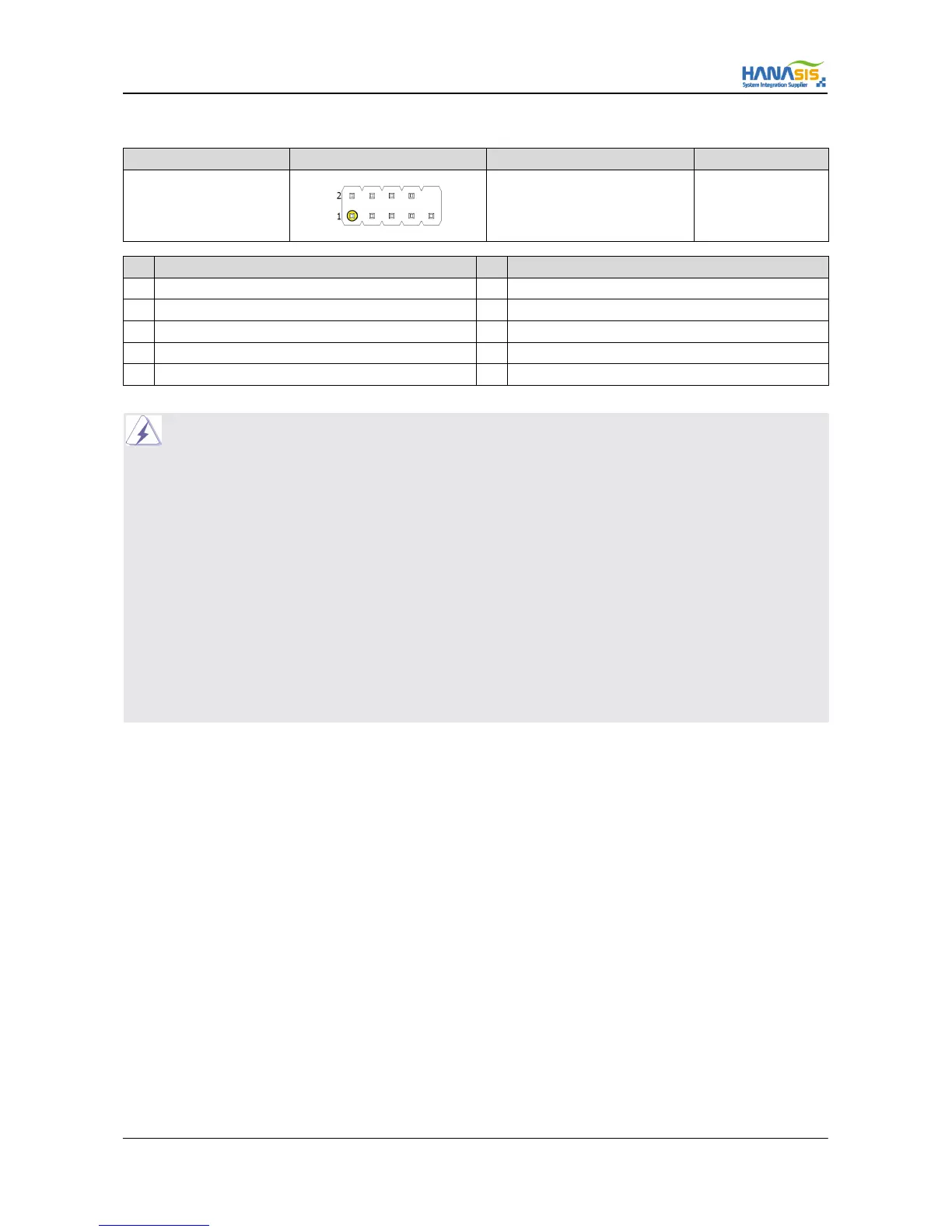
2.6.8 System Front Panel Connector (F PANEL)
Connector SPEC Shape Signal Description Remark
9-Pin 2.54 Pitch
Refer to below
No Signal Description No Signal Description
1 HDD LED (+) 2 PWRLED (+)
3 HDD LED (-) 4 PWRLED (-)
5 RSTBTN (+) 6 PWRBTN (+)
7 RSTBTN (-) 8 PWRBTN (-)
9 DUMMY 10 -
NOTE] This header accommodates several system front panel functions.
Connect the power switch, reset switch and system status indicator on the chassis to this header according to the
pin assignments below. Note the positive and negative pins before connecting the cables.
PWRBTN (Power Button Switch) :
Connect to the power switch on the chassis front panel. You may configure the way to turn off your system using the
power switch.
RSTBTN (Reset Button Switch) :
Connect to the reset switch on the chassis front panel. Press the reset switch to restart the computer if the computer
freezes and fails to perform a normal restart.
PWRLED (System Power LED) :
Connect to the power status indicator on the chassis front panel. The LED is on when the system is operating.
The LED keeps blinking when the sys- tem is in S1/S3 sleep state. The LED is off when the system is in S4 sleep
state or powered off (S5).
HDDLED (Hard Drive Activity LED) :
Connect to the hard drive activity LED on the chassis front panel. The LED is on when the hard drive is reading or writing data.
NOTE] The front panel design may differ by chassis. A front panel module mainly consists of power switch, reset switch, power LED,
hard drive activity LED, speaker and etc. When connecting your chassis front panel module to this header, make sure the wire
assignments and the pin assignments are matched correctly.