Technical Manual VERSION 2.0 -10-18-2018
50
e. Suction and discharge stop valves
For maintenance and service of compressor, it is recommended to install the suction and discharge stop valves.
Please refer to following detail of Hanbell stop valves.
Stop Valve Size
Stop Valve Size
Discharge Suction Discharge Suction
RC2100
1 1/2″ 2″
RC2470
2 1/2″ 4″
RC2140
1 1/2″ 2″
RC2510
3″ 4″
RC2180
1 1/2″ 2 1/2″
RC2550
3″ 4″
RC2200
1 1/2″ 2 1/2″
RC2580
3″ 4″
RC2230
2″ 3″
RC2620
3″ 5″
RC2260
2″ 3″
RC2710
4″ 5″
RC2300
2″ 3″
RC2790
4″ 5″
RC2310
2″ 3″
RC2830
4″ 5″
RC2320
2″ 3″
RC2930
4″ 5″
RC2340
2 1/2″ 4″
RC21020
4″ 6″
RC2370
2 1/2″ 4″
RC21130
4″ 6″
RC2410
2 1/2″ 4″
RC21270
5″ 8″
RC2430
2 1/2″ 4″
RC21530
5″ 8″
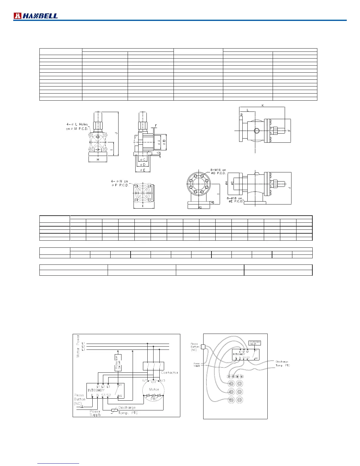
Figure 28 Dimension of stop valve Figure 29 5” Suction stop valve
Dia.
1 1/2
2 1/2
90 110 67 89 111 6 5 137 95 307 153 18 140 M16x2 140
3
100 120 80 99 121 6 5 154 117 398 177 22 160 M20x2.5
160
4
Dia.
5
30 30 126 194 194 248 230 230 214 338 474 161
* Specification of stop valve
Maximum working pressure Hydrostatic pressure test Refrigerant Temperature range
28 kg / cm² G 42 kg / cm² G HFC, HCFC, R717
40˚C~150˚C
f. INT69HBY control module and PTC temperature sensor
In order to protect compressor, each RC2 series compressor has been installed three PTC temperature sensors
inside motor coil and another one at the discharge side of compressor. These sensors are connected to an
INT69HBY control module to monitor the motor and discharge temperature. If the temperature in one of the positions
monitored exceeds the nominal response temperature of the respective PTC thermistor, the sensor resistance
increases and the INT69HBY control module output relay trips. The module resets when the temperature drops
below the response temperature by approx. 5K. The output replay provides a potentialfree changeover contact and
is energized as long as the nominal response temperature is not exceeded.
V/2
W/3
U/1
X/8
Y/9
Z/7
A
B
B Set:Pt100/Pt1000(Optional)
A Set:PTC
Figure 30 INT69HBY & PTC connection diagram