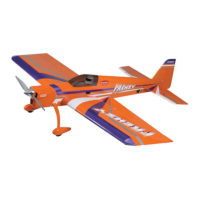
Do you have a question about the Hangar 9 FuntanaX 100 ARF and is the answer not in the manual?
Install servo hardware, extensions, and secure servo leads for proper operation.
Prepare hinges, drill hinge slots, and place hinges in aileron for CA application.
Assemble linkage, attach ball end to servo arm, and position control horn.
Attach control horn, drill holes, apply CA, and adjust linkage for centered aileron.
Install anti-rotation pin, wing tube, and attach wing fillets to fuselage.
Position stabilizer in fuselage, ensure parallelism with wing, and glue in place.
Install vertical stabilizer, check 90-degree alignment to stab, and glue securely.
Install servo extensions, mount servos, and assemble elevator linkage.
Temporarily attach elevator, position control horn, drill holes, and attach horn.
Prepare rudder hinges, assemble linkage, and attach control horn.
Install tail wheel bracket, bearing, and secure tail wheel assembly.
Install landing gear, axle, and attach wheels using collars.
Drill pant screw holes, insert blind nuts, and attach wheel pants.
Attach engine mount to firewall and position engine at specified distance.
Install pushrod tube, connect throttle servo, and adjust linkage for full range.
Access blind nuts, position cowl, and remove material for engine clearance.
Drill screw holes, make cutouts, and attach cowling using screws and washers.
Secure radio tray, install receiver and battery, and connect servo leads.
Mount antenna and switch, attach canopy hatch, and apply decals.
Check and adjust the model's balance point for optimal flight performance.
Adjust linkage and travel for desired control surface movement and mechanical advantage.
Utilize radio rates and expo for fine-tuning flight feel and maneuverability.
Perform a ground range check to ensure reliable radio control before flight.
Seal hinge gaps to prevent flutter and improve control surface effectiveness.
Ensure proper linkage geometry and avoid high-speed dives to prevent structural failure.
Adherence to rules regarding flight operations, safety, and model identification.
Guidelines for radio equipment usage, frequency management, and flying site rules.
| Construction | Balsa and plywood |
|---|---|
| Covering | UltraCote |
| Skill Level | Intermediate to advanced |
| Radio System | 4+ channel |
| Servos | 5 |
 Loading...