EasyManua.ls Logo

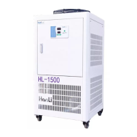
HANLI SCHYTJ-1500 User Manual

Default Icon
28 pages
To Next Page IconTo Next Page
Page #1 background imageLoading...
Page #1 background image
1
User's Manual of Fiber Laser Chiller
HL-1000/1500/2000/3000/4000/6000/8000/12000/15000/20000/30000/40000/50000 Series
SCH-/1500/2000/3000 Series
SCL-/1500/2000/3000 Series
SCHYTJ-/1500/2000/3000 Series
SY-1500/2000 Series
User’s Manual of Fiber Laser Chiller
WUHAN HANLI REFRIGERATION TECHNOLOGY CO., LTD.
Add: No. 1, Second Road, XinFuYua, Hannan District, Wuhan, China
Post Code: 430090 Email: hanli-laserchiller@hanlizl.com
Tel: +86-13682641130
www.hanlichiller.com

Questions and Answers:

HANLI SCHYTJ-1500 Specifications

General IconGeneral
BrandHANLI
ModelSCHYTJ-1500
CategoryChiller
LanguageEnglish

Summary

General Safety Warnings

Safety Precautions for Professional Personnel

Ensures operations are performed by qualified professionals to prevent injury.

High Voltage and Scald Risk Warnings

Identifies risks associated with high voltage and hot surfaces.

Electrical Connection Safety

Details requirements for power supply, cables, and grounding.

Maintenance and Scrap Safety

Outlines safe practices for maintenance and equipment disposal.

Operational Restrictions

Specifies limits on usage, environment, and component integrity.

Transport and Installation Safety

Ensures secure equipment handling during transport and installation.

Operational Fault and Refrigerant Safety

Addresses hazards from abnormal operation and refrigerant leaks.

Handling and Environmental Guidelines

Covers proper handling, tilt limits, and environmental installation constraints.

Operational Checks and Maintenance Safety

Lists pre-operation checks and safety during maintenance.

Operating Conditions

Installation Guidelines

Installation Conditions and Requirements

Checks upon unpacking and requirements for stable, safe installation.

Equipment Installation Form Requirements

Illustrates correct and incorrect equipment installation forms.

Installation Space Requirements

Specifies clearance needed for air suction and exhaust for proper heat dissipation.

Waterway Connection Procedures

Electrical Circuit Connection

Adding Water and Air Exhaust

Product Operation and Commissioning

Parameter Setting Procedures

Routine Maintenance

Fault Analysis and Troubleshooting

Fault Codes and Descriptions

Lists fault codes (E01-E07), failure analysis, movement, and exclusion methods.

Fault Codes and Troubleshooting (Continued)

Details faults E08-E12, probe/flow issues, and LCD controller faults.

LCD Controller Fault Names and Reset

Lists LCD controller faults, testing conditions, troubleshooting, and reset methods.

LCD Controller Faults and Reset Procedures

Covers probe, water flow switch, and water level switch alarms and their resets.

Circuit Diagrams

Transportation and Storage Guidelines

Related product manuals