DG3 Controller – Installation and Operation
Manual
540846-3 page 11 of 64 25/09/2015
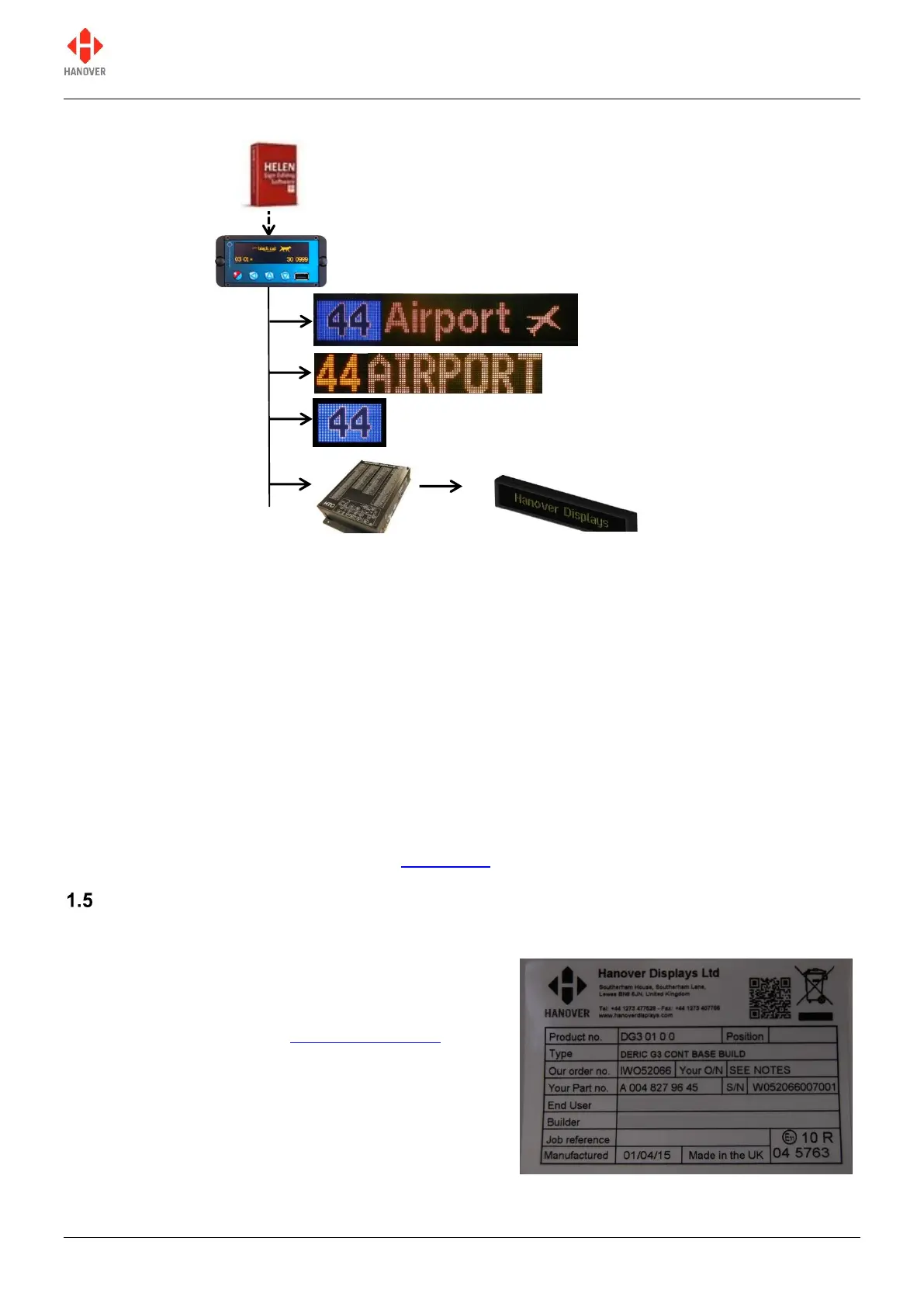
Figure 1 - diagram showing typical controller / signs configuration. Each unit is powered individually.
Figure 2 - diagram showing a communications network which includes an on-board computer
A database of information for all signs within a system is created on a standard Windows PC, using Helen
software. The database is then uploaded to the controller. Each sign has a processor with an address
switch that is associated with the configuration for that sign set within Helen. This allows it to receive the
appropriate information via the DG3 which is connected to the sign by a multi-drop communications
network.
Note that any DG3 configuration parameters set in Helen that are loaded into the controller will be
overwritten by any manual changes to those parameters made later directly via the controller itself. Further
list downloads may overwrite such manual changes.
Note also that any manual alterations that conflict directly with Helen-programmed parameters should be
avoided as the results are unpredictable.
Full technical details are provided in section 3 Operation.
Identification
The controller's identification can be determined from the silver label on the casing.
In addition to identifying the model, it may be necessary to
determine the software version installed, especially for
technical support queries. To ascertain the version in use,
go to 'Show status' in section 3.5.1 Status options.
Figure 3 – silver label on casing of controller
Destination sign(s) (side)
 Loading...