DG3 Controller – Installation and Operation
Manual
540846-3 page 14 of 64 25/09/2015
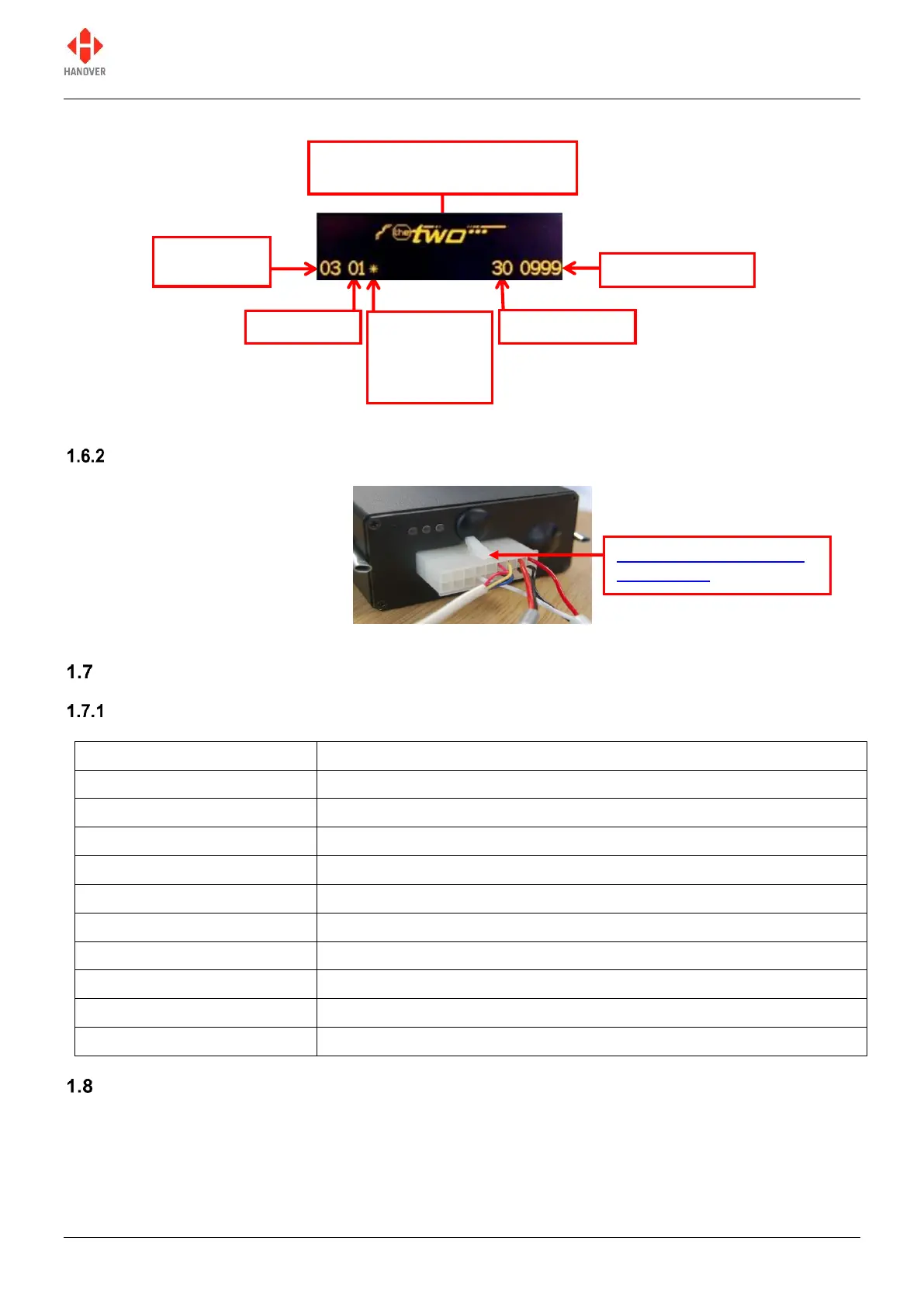
1.6.1.1 Example of an organic LED display
Figure 5 - diagram showing an example of LED display of the controller
Rear view
Figure 6 - diagram showing the rear side of the controller
Technical information
Specification
Dashboard / panel using DIN clamps or screw fixing
Depth required (behind panel)
high resolution 256 x 64 pixels with one, two or three lines of text
0.15A @ 24Vdc (approx. 3.6W)
Operating temperature range
System supply voltages
All Hanover 24V devices are suitable for the full voltage supply range found on vehicles with a 24V battery.
Some Hanover signs and controllers are compatible with 12V systems. For supply voltage details, please
refer to the technical information for a specific product.
Content of front sign or driver
message for current destination
* displayed if
there is one
or more sign
errors
Appendix A: 18-way mini
fit connector
 Loading...