Fitting and installation
Page EN-29
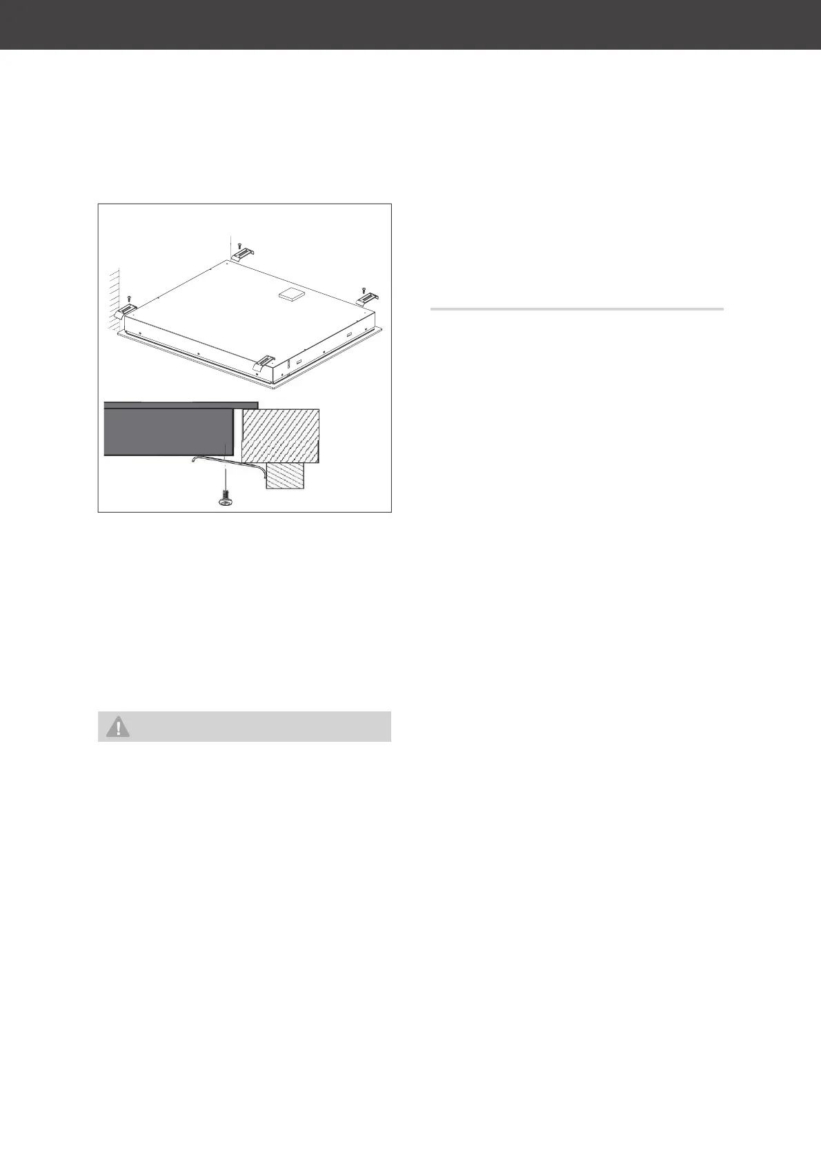
Thick worktop
6. Screw the four retaining clamps, accord-
ing to the thickness of the worktop, into
the hob from below. This will prevent the
hob from moving.
Connection to the power
supply – notes for the installer
WARNING
Electric shock / fi re hazard!
Improperly installed electrical connec-
tions can cause electrical shocks and/or
short circuits.
■ Connection to the mains supply may
only be made by an authorised elec-
trician approved by the local energy
supply company, e.g. our Service Cen-
tre (see page EN-34). Only then will
you benefi t from our warranty and a
suffi cient level of safety.
■ Since all poles of the appliance can-
not be disconnected from the mains
via an accessible disconnecting de-
vice, an all-pole disconnecting device
in accordance with overvoltage cat-
egory III must be connected within
the house installation with at least 3
mm contact clearance; this includes
fuses, miniature circuit breakers and
protective devices.
Connection conditions
– The rated voltages allowed as well as the
rating of the device can be found in Chapter
„Technical specifications“ on page EN-40.
– Depending on the type of connection al-
lowed, you must
– select the cross-section cable
– insert or remove contact bridges
(see table and circuit diagrams on the
right).
– The power cord used must comply with
the requirements of DIN EN 60335-1 (e.g.
H05RR-F model).
– A separate power supply is required.
– When connecting the appliance, VDE re-
quirements and the “Technical connection
requirements” must be observed.
Contact protection must be guaranteed.
Connecting to the mains
The terminal block and connection diagrams
can be found on the rear side of the oven.
1. Before accessing the terminals, switch off
all supply circuits and secure them against
being switched on again.
2. Make sure that all poles of the connection
cables are disconnected and that effective
earthing is possible.
3. Connect the leads and, if necessary, the
enclosed brass bridges to the correspond-
ing contact terminals of the cooker power
connection in accordance with the circuit
diagrams shown here.
4. Lay the connection cable behind the cook-
er so that it does not touch the rear wall of
the cooker. The rear cooker wall becomes
hot while it is in use.