OPERATING DATA
===================================================
@
INSTALLATION - The
monitor
is provided
with
inputs
as
listed
below:
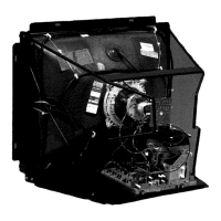
1.
POWER SUPPLY -
Connect
128
Va.
c.
50/60 Hz via an
isolating
transformer
capable
of
delivering
0.75A
to
terminals
1 and 2
with
connector
CB.
2.
DEGAUSSING CIRCUIT -
Connect
the
mains
(220 V
or
110 V a.c.)
direct
to
terminals
3 and 4
of
connector
CB,
the
degauss-
ing
coils
to
terminals
1 and 2
of
connectors
CD,
the
degaussin
pushbutton
to
terminals
1 and 2
of
connector
CC. The
pushbutton
is
mounted
on a
bracket
and
connected
by a
flying
lead and
should
be
placed
in a
position
which
is
accesible
from
the
outside.
3.
RGB VIDEO SIGNALS -
Connector
CA Terminal 1 blue
input;
Terminal 2 green input; Terminal 3 red input. For POSITIVE
video
signals
connect
CX
to
position
A,
for
negative
video
connect
CX
to
position
B
4. SYNCHRONISATION SIGNALS -
Connector
CA: Terminal 6
composite
(H
+
V)
or
vertical
sync., Terminal 5
horizontal
sync.,
Terminal 4
ground.
For
positive
sync.
switch
CY
to
A,
for
negative sync.
switch
CY
to
B;
5.
CALIBRATION OF VIDEO INPUT LEVELS -
Connect
the
signals
to
the
RGB
inputs
and
adjust
RVI
for
BLUE, RV2
for
GREEN,
RV3
for
RED
until
2Vpp ±
5%
is
obtained
at
TP1
- TP2 - TP3 respectively.
6.
BRIGHTNESS AND CONTRAST -
After
having
correctly
connected
the
power
supply
and
the
input
signals,
briefly
press
the
degaussing
button,
then
adjust
the
brightness
and
contrast
for
a
satisfactory
picture.
These
controls
which
are
mounted
on a
bracket
are removable by
unscrewing
the
screws
5 (Fig.
X)
and may be
mounted
remote from
the
chassis.
If
after
this,
further
adjustment
is required, refer
to
Fig. X
for
the
position
of
the
various
controls
and
to
the
alignment
instructions
to
obtain
correct
adjustment.
All
the
input
signals
must
have
the
characteristics
described
in Table
X.
CD
INSTALLAZIONE - II
monitor
viene
fornito
con
gli
ingressi
predisposti
net
modo
sottoelencato:
1.
ALIMENTAZIONE -
Collegare
128 V
CA
50160
Hz
tramite
un
trasformatore
isolatore
capace
di
erogare 500 mA
ai
terminali
1
e 2
col
connettore
CB.
2.
C/RCUITO DI SMAGNETIZZAZIONE - Collegare la rete
diretta
(220V o 110V
CA
ai
terminali
3 e 4 def
connettore
CB. le bobi-
ne
di
smagnetizzazione
ai
terminali
1 e 2 def
connettore
CD,
ii
pulsante
di
smagnetizzazione
ai
terminali
1 e 2 de/
connetto-
re CC -
ii
pulsante
e
asportabile
e
va
pasta
in
posizione
accessibile
dall'esterno.
3.
SEGNALI VIDEO RGB -
Connettore
CA; terminate 1
ingresso
bleu;
Terminate 2
ingresso
Verde, Terminate 3
ingresso
rosso.
Per
segnali
video POSIT/VI
porre
CX in
posizione
A,
per
video
negativo
CX
in
B.
4.
SEGNALI DI SINCRONIZZAZIONE -
Connettore
CA
terminate
6
sinconismo
verticale
composito
(H
+
V)
terminate 5
sincroni-
smo
orizzontale. Terminate 5 massa. Per
sincronismo
positivo,
commutare
CY in
A,
per
sincronismi
negativi
CY in
B.
5. TARATURA LIVELLI DI INGRESSO VIDEO - Col/egare i
segnali
agli
ingressi
RGB a regolare
RV1
per
ii
BLU , RV2
per
ii
VER-
DE,
RV3
per
ii
ROSSO,
fino
ad
ottenere
1
Vpp
±
5%
sui
TP1
-TP2 -
TP3
rispettivamente.
6.
LUM/NOS/TA E CONTRASTO - Dopa avere
correttemente
collegati
l'alimentazione
ed i
segnali
di
ingresso,
premere
ii
pu/-
sante
di
smagnetizzazione
e regolare
quindi
la
luminosita
ed
ii
contrasto
in
maniera
da avere una
immagine
soddisfacente.
Tali
comandi
sono
asportabili
mediante
l'estrazione
de/le
viti
(fig.
X)
e
possono
essere
portati
in
posizione
accessibile
dall'esterno
dell'apparecchiatura.
Net
caso
che
dopo
queste
regolazioni
ii
monitor
necessitasse
di
alcuni
ritocchi,
riferirsi
al/a figura X
per
la
posizione
dei
va-
ri
comandi
ed
a/le
istruzioni
di
taratura
per
un
corretto
aggiustamento
.
Tutti
i
segnali
di
ingresso
debbono
avere le
caratteristiche
descritte
in TAB
X.
®
INSTALLATION:
Le
moniteur
est fourni avec les entrees
predisposees
de la fagon suivante:
1.
ALIMENTATION: relier 128 VGA 50/60 Hz au moyen
d'un
transformateur
isolant
capable
de
fournir
500
mA
aux
extremites
1
et 2 avec
le
connecteur
CB.
2.
CIRCUIT
DE
DEMAGNETISATION: relier le reseau
direct
(220 V ou
i10
v CA) aux
extremites
3 et 4 du
connecteur
CB, les
bobines
de
demagnetisation
aux
extremites
1 et 2 du
connecteur
CD, le
bouton
de
demagnetisation
aux
extremites
1 et 2
du
connecteur
CC. Le
bouton
est
amovible
et se
met
en
position
accessible
de
l'exterieur.
3.
SIGNAUX VIDEO
RGB:
Connecteur
CA,
extremite
1,
entree bleue,
extremite
2 entree verte,
extremite
3,
entree rouge. Pour
des
signaux
video POSITIFS
mettre
C en
position
A;
pour
video NEGATIF, CX en B/
4. SIGNAUX DE SYNCHRONISATION:
connecteur
CA
extremite
6
synchronisme
vertical
composite
(H
+
V)
extremite
5
~1
synchronisme
horizontal,
extremite
de masse. Pour
synchronisme
posit
if,
changer
CY en
A,
pour
synchronisme
negatif
CY
en
B.
5. REGLAGE NIVEAUX D'ENTREE VIDEO: relier les
signaux
aux entrees RGB et regler
RV
1
pour
le bleu,
RV
2
pour
le vert,
RV
3
pour
·
1e
rouge
jusqu'a
l'obtention
de 1 Vpp ±
5%
sur
respectivement
TP1, TP2, TP3.
6.
LUMINOSITE
ET
CONTRASTE: apres avoir
correctement
relie
l'alimentation
et les
signaux
d'entree, appuyer le
bouton
de I
demagnetisation
et regler la
luminosite
et le
contraste
de fagon a
obtenir
une
image
satisfaisante.
Ces
commandes
sont
amovibles
grace
a
!'extraction
des vis (fig.
X)
et peuvent etre placees en
position
accessible
de
l'exterieur
de
l'appareillage.
I
Si
apres ces reglages le
moniteur
necessite
quelques
retouches
, se reporter a la
figure
X
pour
la
position
des
differentes
comm
.
9ndes
et
aux
instructions
de reglage
pour
un
ajustement
correct.
Tous
~
les
signaux
d'entree
doivent
avoir les
caracteristiques
decrites
dans
TAB
X.
I
8 i
 Loading...