Do you have a question about the Hantarex MTC 9110 and is the answer not in the manual?
Designed for maximum versatility, adaptable to any logic board.
Single PCB design for automatic component insertion, ensuring uniformity and reliability.
New design for enhanced resistance to impact and vibration during transportation.
Two connectors for easy image inversion and reversal.
Thermostat on heat sink interrupts 130V DC if temperature reaches 75-80°C.
Controls mounted on separate PCB, can be extended with a cable for front mounting.
Precision potentiometer accepts signals from 1 to 5V p.p. without color balance changes.
New integrated circuit (TDA 1670A) for short vertical fly-back time (0.7ms).
New IC for horizontal sync, provides x-ray protection and meets health regulations.
Input supply must be fed via a mains isolating transformer.
Chassis and heat sinks are earthed; connect instruments to chassis for measurements.
Designed to minimize x-ray radiation; safety circuit limits radiation to below 0.5 mR/h.
High voltages present; follow all safety instructions and warnings.
Handle CRT with care due to vacuum and pressure; wear protective gear.
Do not expose to rain or excessive humidity to avoid electric discharge.
Details on the x-ray protection circuit using TDA 2595 for EHT overvoltage shutdown.
128 V a.c. (±10%), 50/60 Hz. Requires specific isolating transformer.
100 W max.
100-264 V a.c. automatic; manual control option available.
RGB positive-going, 2.2 kOhm impedance, 1-5 V p.p. sensitivity.
-3 dB at 12 MHz.
Horizontal/vertical, composite/separate, 2.2 kOhm impedance, 1.5-5 V p.p.
Horizontal 15.625 ± 0.5 kHz (adjustable), Vertical 45-65 Hz (adjustable).
List of controls: contrast, brightness, focus, frequency, phase, amplitude, linearity, shift.
Verify HT line voltage at TP10 is 130 V d.c. ± 3%.
Adjust RV5 for a stationary image after removing sync signal.
Adjust RV1 for slow image roll-over until locked.
Check voltage at TP13 is 26 V d.c. ± 5%.
Check voltage at TP1 is 24 V d.c. ± 5%.
Check voltage at TP14 is 200 V d.c. ± 5%.
Procedure for re-adjusting Bridge Coil B3 using RV4.
Adjust RV401 for best vertical geometry.
Adjust gain controls for equal amplitude at cathodes.
Procedure for setting brightness, black level, and white balance.
Adjust focus control for best focus using a dot pattern.
Adjust for equal square size on grid pattern.
Insert supply cable to power input connector CC.
Insert signal and sync cable to input connector CA.
Set SW4 to positive or negative for locked image.
Adjust amplitude, frequency, phase, brightness, contrast.
Diagram showing mains connection via isolation transformer for USA.
Describes controls on the remote board and extension cable availability.
List of components for the main printed circuit board.
List of components for the CRT socket assembly.
List of components for the controls PCB assembly.
List of components for power wiring assembly.
List of components for signals input wiring assembly.
List of components for the 25" CRT assembly.
List of components for the ventilator assembly.
List of components for the 28" CRT assembly.
List of components for the impedance adaptor PCB.
List of components for the yoke wiring assembly.
List of components for the 25" degaussing coil assembly.
List of components for the 28" degaussing coil assembly.
List of components for the 25" CRT mainframe assembly.
List of components for the 28" CRT mainframe assembly.
List of components for the 25" packing assembly.
List of components for the 28" packing assembly.
List of components for the East-West PCB assembly.
Detailed list of components for the main PCB.
Detailed list of components for the CRT socket PCB.
Detailed list of components for the controls PCB.
Detailed list of components for power wiring.
Detailed list of components for signals input wiring.
Detailed list of components for the 25" CRT assembly.
Detailed list of components for the ventilator assembly.
Detailed list of components for the 28" CRT assembly.
Detailed list of components for the impedance adaptor PCB.
Detailed list of components for the yoke wiring assembly.
Detailed list of components for the 25" degaussing coil assembly.
Detailed list of components for the 28" degaussing coil assembly.
Detailed list of components for the 25" CRT mainframe assembly.
Detailed list of components for the 28" CRT mainframe assembly.
Detailed list of components for the 25" packing assembly.
Detailed list of components for the 28" packing assembly.
Detailed list of components for the East-West PCB assembly.
Schematic illustrating the main printed circuit board components and connections.
Schematic detailing the video signal processing and color control circuitry.
Functional block diagram for the TDA 2595 integrated circuit.
Functional block diagram for the TDA 1670A integrated circuit.
Table providing overall dimensions (A, E, G, M, Y) in mm and inches.
Visual representations of test point signals (TP2, TP3, TP4, TP5, TP8, TP9, TP11).
List of test point voltages and their associated supplies.
Descriptions of waveforms at various test points (T.P.2 to T.P.11).
Detailed list of test point voltages and their descriptions.
Connections and adjustments for degaussing coil and horizontal yoke.
Connections and adjustments for vertical yoke.
Connections and adjustments for Red Gain and Green Cut-Off.
Connections and adjustments for Red Cut-Off and Blue Cut-Off.
Connections and adjustments for Blue Gain and G2 Screen.
Connections and adjustments for Focus and Grounding.
Connections and adjustments for Bridge Coil and Control Module.
Connections and adjustments for Vertical Frequency and Horizontal Amplitude.
Connections and adjustments for Horizontal Width and Vertical Amplitude.
Connections and adjustments for Vertical Phase and Horizontal Shift.
Connections and adjustments for Horizontal Phase and Vertical Frequency.
Connections and adjustments for Video/Sync Input and Contrast.
Connections and adjustments for Contrast and Sync Polarity Switch.
Connections and adjustments for East/West adjustment.
Connections and adjustments for the KK module East/West correction.
Connections and adjustments for the brightness preselector.
Connections and adjustments for horizontal linearity.
Explains the interface board for negative video signals and its ordering code.
Circuit diagram of the Inverter Video board.
Details on available power supply transformers for the monitor.
Information on power and signal connection leads supplied with the monitor.
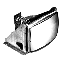
Description of a metal support for fixing the electronic chassis.
Specifications for the 10-inch MTC9000 monitor model.
Specifications for the 14-inch MTC9000 monitor model.
Specifications for the 15-inch MTC9000 monitor model.
Specifications for the 16-inch MTC9000 monitor model.
Specifications for the 20-inch MTC9000 monitor model.
Details on the US 250 switched mode power supply.
Details on the US 300 ventilated switched mode power supply.
Description of the RGB signal generator for setup.
| Deflection Angle | 90° |
|---|---|
| Category | Monitor |
| Input | RGB |
| Display Type | CRT |
| Screen Size | 20 inch |