OPERATING INSTRUCTIONS
1)
Insert the supply cable
to
the power input connector
CC.
See page
37.
2)
Insert the signal and sync. cable to the input connector
CA.
See page
37.
3)
Set sync. selector switch SW4
to
positive or negative according
to
the type of input signal.
~o:
As
to
obtain a locked image horizontally and vertically. See page
37.
4)
Next adjust vertical amplitude, vertical frequency, horizontal amplitude, horizontal phase, vertical shift,
horizontal frequency, East-West, brightness and contrast
to
match the applied signal. See page
37.
Finally
it
may
be
necessary
to
trim
to
the colour and white adjustments. See para. 9 and 1 O page 1
O.
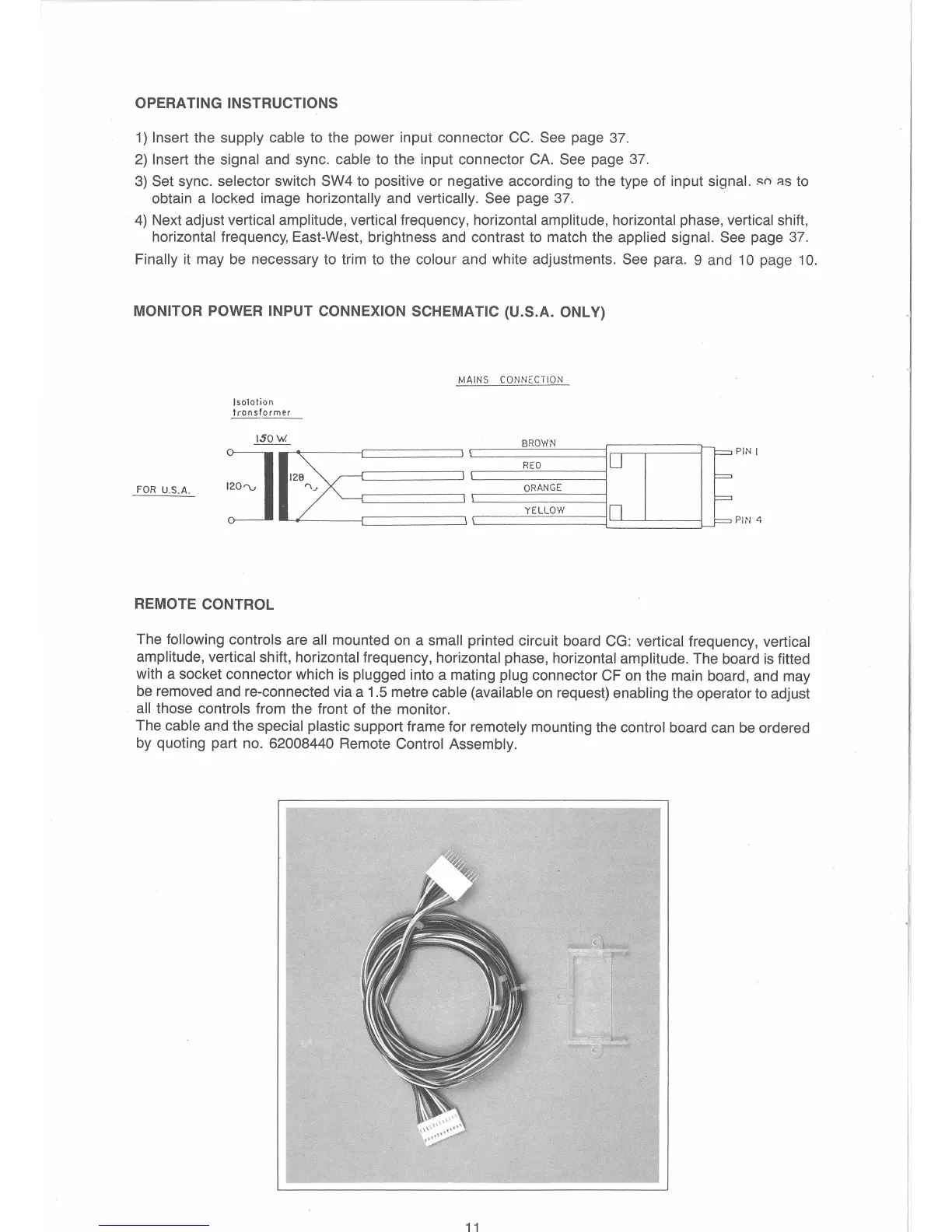
MONITOR POWER
INPUT
CONNEXION SCHEMATIC (U.S.A. ONLY)
FOR U.S.A.
Isolation
Irons
former
-----
REMOTE CONTROL
MAINS CONNECTION
PIN
I
PIN 4
The following controls are all mounted
on
a small printed circuit board
CG:
vertical frequency, vertical
amplitude, vertical
shift, horizontal frequency, horizontal phase, horizontal amplitude. The board
is
fitted
with a socket connector which
is
plugged into a mating plug connector CF
on
the main board, and may
be
removed and re-connected via a 1.5 metre cable (available
on
request) enabling the operator
to
adjust
all those controls from the front of the monitor.
The
cable and the special plastic support frame for remotely mounting the control board can
be
ordered
by quoting part no.
62008440 Remote Control Assembly.
11
 Loading...