78
Note: It is not possible to calibrate the diode or continuity separately because these
functions are based on calibrated resistance measurements. In addition, there is no way to
calibrate the gate timing because this function is controlled by digital logic. Capacitance
gain cannot be calibrated.
Precautions for Testing
During self-testing, an error may be raised if an AC signal appears on the input lead. If the
test lead is too long, it can also cause AC signal display.
To optimize performance:
Ensure that the calibration ambient temperature (TCAL) is constant and between 18
℃and 28 ℃. The ideal calibration temperature should be 23 ℃, fluctuating 2 ℃.
Ensure that the ambient relative humidity is below 80%.
The connecting copper cable requires a preheating time of 90 minutes.
Connect the input cable shields to the ground. Connect the calibrator LO source to the
ground in addition to the where noted in the procedures. It is important to avoid a
ground loop by connecting the LO to the ground at only one point in the circuit.
Because the instrument is capable of very precise evaluation, you must be extra careful to
ensure that the calibration standards and test procedures used do not cause other errors.
Ideally, the criteria used to validate and adjust equipment should be more accurate than
the error specifications for equipment of all sizes.
For 2-wire resistance measurements, take a null measurement with a short-circuited
lead or high precision 4 terminal low thermal short-circuit
to remove wire resistance.
For zero offset calibration, a 4 terminal low thermal short circuit is required.
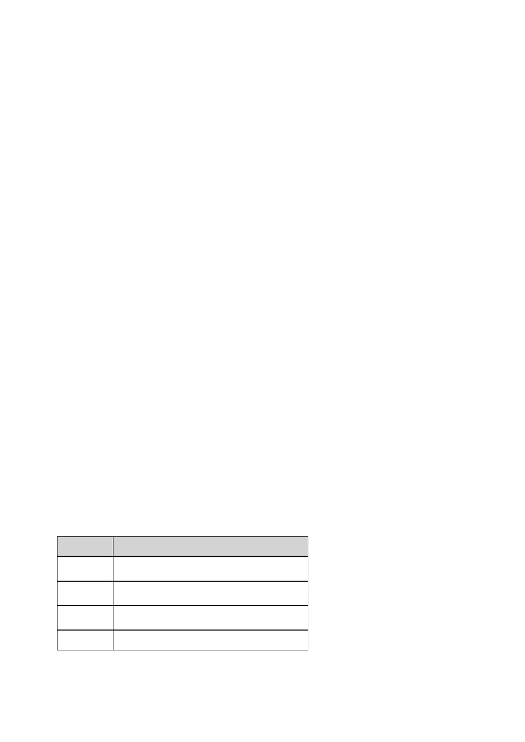
Recommended testing equipment
The recommended testing equipment for performance verification and calibration is listed
below. If the required equipment is not available, replace it with a calibration standard with
the same accuracy.
High precision 4 terminal low thermal short-
circuit
 Loading...