2
Part name and functions
⑪
⑫
⑬
①
②
③④⑤⑥⑦
⑭
⑧⑨⑩
⑪
⑫
①
②
③④⑤⑥⑦
⑭
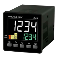
LT4S
INHIBIT
START
RESET
0 V
1
3
4
2
12-24 V d.c.
LT4S
INHIBIT
START
RESET
0 V
1
3
4
2
12-24 V d.c.
LT4S
RESET
0 V
2
4
START
3
INHIBT
1
● Contactless input
(when the sensor output is NPN open
collector output)
● Contact input
●Contactless input
(when the sensor output is NPN voltage output)
* LT4S model is non-voltage input type (NPN input)
* Each input terminal is not isolated from the power terminal
* When you set CONT to 1c in function setting mode,
OUT1 operates as instantaneous output.
* When you set O-MD to S-D in function setting mode,
OUT1 operates as
output, and OUT2 operates as
output.
Input connection
No Name Usage
① PV display
• displays time value in POND / PINT / SOND / SINT /
SOFD / S.OND / S.INT/ S.ODR operation modes
• displays set value and time value in PFKF / PFKN / TWON /
TWOF / S-D / SFKF / SNFN / SNFF / S.FKN operation modes
• displays setting items in function setting mode
② SV display
• displays set value in POND / PINT / SOND / SINT /
SOFD / S.OND / S.INT / S.ODR operation modes
• displays set value and time value in PFKF / PFKN / TWON /
TWOF / S-D / SFKF / SNFN / SNFF / S.FKN operation modes
③ MODE KEY
enters and quits function setting mode
(automaticaly saves function set value during termination)
④ SHIFT KEY
enters set value change mode and shifts the set value digits
⑤ DOWN KEY
reduces set value in function setting mode and set value
change mode
⑥ UP KEY
increases set value in function setting mode and set value
change mode
⑦ RESET KEY
initializes time value and output status
⑧
START input indicator
illuminates when external START signal is applied
⑨
INHIBIT input indicator
illuminates when external INHIBIT signal is applied
⑩
RESET input indicator
illuminates when external RESET signal is applied
⑪ LOCK set indicator
illuminates when LOCK is set
⑫
timer operation indicator
flashes during timing operation
⑬ O1 output indicator
illuminates during OUT1 output operation
⑭ O2 output indicator
illuminates during OUT2 output operation
In LT4S models, it illuminates during OUT output operation
Dimension and panel cutout
Connection diagram
3.50
5.00
51.20
56.20
14.50
11.10
44.60
48.00
48.00
●LT4
●LT4 (STAR-DELTA)
●LT4S
sensor sensor
POWER
(-) (+)
OUT1 OUT2
POWER
(-) (+)
POWER
(-) (+)
OUT
INHIBIT
START
RESET
■LT4 ■LT4S
60 min.
60 min.
15
15
45
45
+0.6
-0.0
+0.6
-0.0
● Dimension
[Unit :㎜]
● Panel cutout
 Loading...