6 7
ASSEMBLY INSTRUCTIONS ASSEMBLY INSTRUCTIONS
1
4
5
3
6
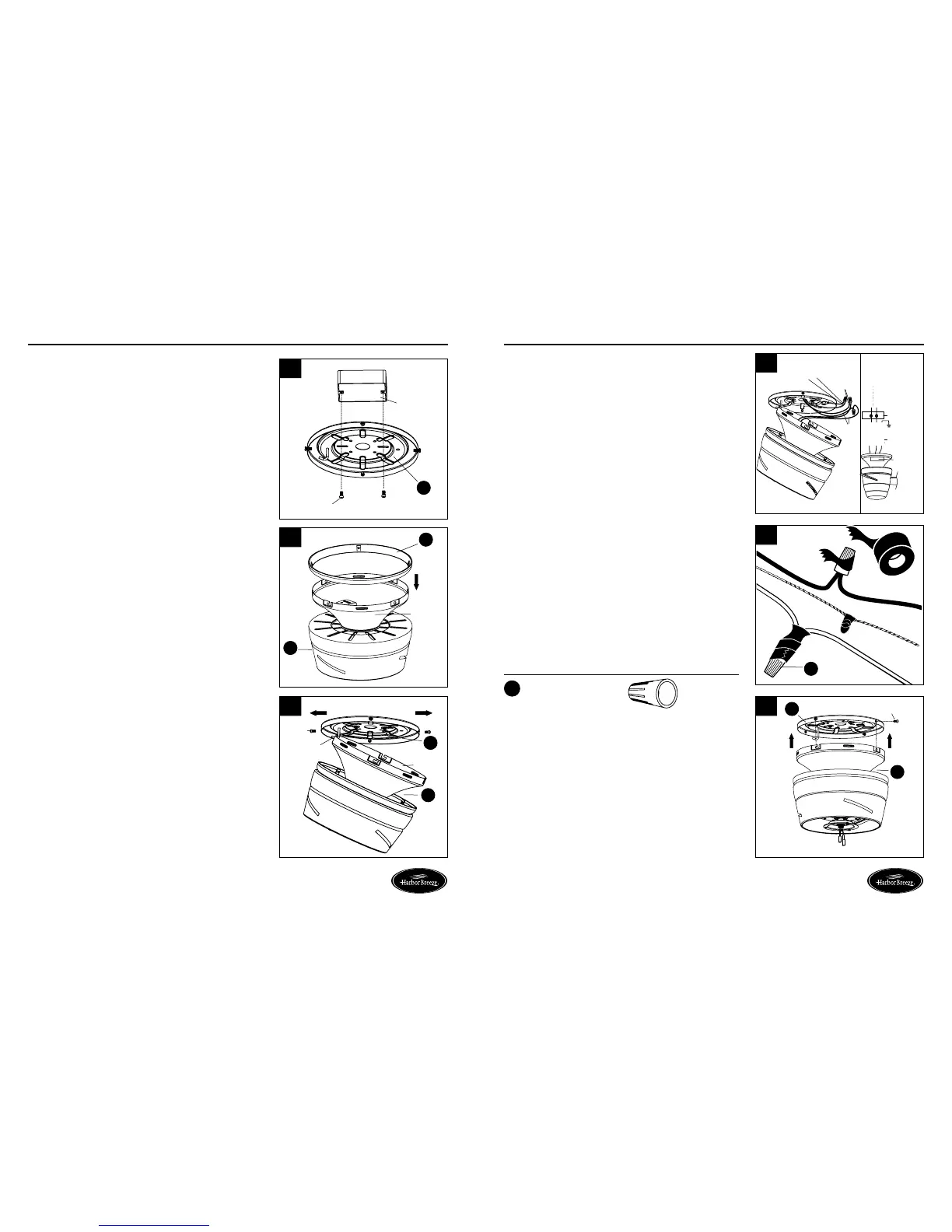
1. Attach mounting plate (A) to outlet box (not included)
using two screws (not included). Securely tighten two
outlet box screws. Pull black, white, and grounded
wires out of outlet box and through the hole in the
mounting plate (A).
2. Place trim ring (C) over canopy, and lay it on fan
motor (B).
3. Loosen two preassembled screws across from each
other on the mounting plate (A). Remove and save
remaining two preassembled screws. Hang fan motor (B)
on mounting plate (A) hook using one of the non-slotted
holes in the canopy.
4. Connect BLACK wire from fan to BLACK wire from
ceiling. Connect WHITE wire from fan WHITE wire
from ceiling. Connect all GROUNDED (GREEN) wires
together from fan GREEN/GROUNDED wire from ceiling.
Connecting the GREEN/GROUNDED wires is conducive
to receive the signal of the remote control.
Note: Black wire is hot power for fan and light kit. White
wire is common for fan and light kit. Green wire is
grounded wire. lf house wires are different colors
than referred to above, stop immediately and consult a
professional electrician to determine proper wiring.
6. Align keyholes on fan motor (B) with protruding screw
heads on mounting plate (A). Lift fan motor (B) up to
mounting plate (A), making sure not to break any wire
connection. Rotate clockwise until screw heads fully
engage into keyholes. Insert previously removed screws
(Step 3, page 6) and securely tighten all screws.
A
A
B
B
B
A
C
B
Outlet box
Screw
2
Hardware Used
x 4
Wire Connector
AA
AA
Canopy
Canopy
Screw
Hook
Grounded/
Green
White
Black
outlet box
black
white
green
white
GREEN/
GROUNDED
black
Supply circuit
receiver
Screw
Lowes.com/harborbreezeLowes.com/harborbreeze
5. Twist wire ends together and screw wire connectors (AA)
on in a clockwise direction. Tape wire connectors (AA)
and wires together.
Note: Wires should be spread apart with grounded
conductor and equipment-grounding conductor on one
side of outlet box and ungrounded conductor on other
side. After making connections, make sure bare wire
or wire strands are NOT visible. Place green and white
connections on opposite side of box from black and
blue connections. Splices should be turned upward and
pushed carefully up into outlet box.
Black
Black
White
Green
Outlet box
Green/
Grounded
Receiver
White
 Loading...