C
Carl GarciaAug 8, 2025
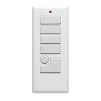
What to do if the Harbor Breeze Fan remote control doesn’t work?
- CCrystal LarsonAug 8, 2025
If your Harbor Breeze fan's remote control isn’t working, first try syncing the remote with the fan's receiver by pressing and holding the high and low speed buttons simultaneously for 5 seconds until the LED indicator flashes 3 times, after which the fan should start on low speed and the light (if applicable) will turn off. If that doesn't work, replace the battery in the remote with a 12V battery.