Do you have a question about the Harbor Breeze 42224 and is the answer not in the manual?
Best suited for ceilings 8 ft. or higher. May require a longer downrod for taller ceilings.
Best for angled or vaulted ceilings. Ensure ceiling angle is not steeper than 10°.
Covers set screw checks, blade handling, fan direction change, common sense, and outlet box support requirements.
Emphasizes shutting off power, blade height, outlet box mounting, and avoiding dimmer switches.
Turn off power, remove mounting bracket from canopy, and retain screws for later use.
Install mounting bracket to outlet box using provided screws. Ensure it's marked for fan support.
Remove motor screws from the underside of the motor assembly and save for blade arm installation.
Prepare downrod, insert through canopy/yoke cover, feed wires, and secure into yoke with pin and clip.
Install downrod ball into mounting bracket, ensuring tab aligns with slot. Insert receiver into bracket.
Connect fan and receiver wires to supply wires using connectors, following the wiring diagram.
Align canopy with J-shaped slots, turn clockwise, and secure with screws.
Attach blades to blade arms using screws and washers, tightening each screw.
Attach blade arms to the motor assembly using the previously removed motor screws. Tighten securely.
Feed connector through light pan, align slots, and secure light pan to fitter plate.
Connect light pan to light kit, secure light kit, and twist glass bowl clockwise until secure.
Remove cage screws, lift light cage over screws, turn clockwise, and reinstall screws.
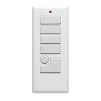
Insert CR2032 batteries into the remote, ensuring positive pole faces up, then replace the battery door.
Install wall bracket if desired. Turn on electrical power. Installation is complete.
Details on operating the fan and light using remote buttons like Fan Off, Light Control, Speed, Delay, Breeze, and Home Shield.
Instructions on syncing the remote to the receiver by pressing the LEARN button.
Guide to downloading and using the Fansio app for WiFi control, noting 2.4 GHz compatibility.
Explains how to use the reverse switch for summer (sun icon, downward airflow) and winter (snowflake icon, upward airflow).
Troubleshooting steps for when the fan fails to start, checking power, wiring, and switch position.
Solutions for fan noise, focusing on screw tightness, wire connector placement, and variable speed controls.
Steps to address fan wobble, including checking screw tightness and blade balancing.
Troubleshooting for the light, checking connectors and the blue wire connection.
Steps for re-syncing the remote, replacing batteries, and performing a factory reset.
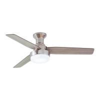
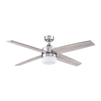
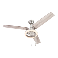
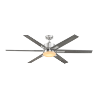
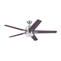
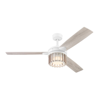
The Elmhurst Ceiling Fan is a versatile and stylish overhead fan designed to provide comfort and illumination in various indoor settings. It offers two primary mounting options: Downrod Mount and Angled Ceiling Mount, catering to different ceiling heights and architectural styles. The Downrod Mount is ideal for ceilings 8 feet or higher, with an option for a longer downrod (not included) for taller spaces. The Angled Ceiling Mount is suitable for angled or vaulted ceilings, provided the ceiling angle does not exceed 10 degrees, and may also require a longer downrod for proper blade clearance.
The fan's operation is managed through a remote control, offering a range of functions for both fan speed and lighting. Users can turn the fan off, control the light (on/off, dim/brighten for dimmable bulbs), and select from various fan speeds: High, Medium, and Low. A unique "Variable Breeze" feature simulates a natural breeze, while "Light Delay" keeps the light on for 60 seconds to allow for safe exit from a room. The "Home Shield™" function simulates occupancy by randomly turning the light on and off, with the fan remaining off, to enhance home security when away. An LED indicator on the remote confirms button presses, and if it doesn't illuminate, the CR2032 batteries should be replaced. The remote also includes a "LEARN" button for syncing with the receiver, accessible by removing the battery door. For advanced control, the fan can be operated via a WiFi remote by downloading the "Fansio®" app, which requires a personal WiFi network name and password and is compatible only with 2.4 GHz routers.
The fan also features a reverse switch, allowing users to optimize airflow for different seasons. In warmer weather, pushing the reverse switch to the left (displaying a sun icon) creates a downward airflow, generating a wind chill effect. In cooler weather, pushing the switch to the right (displaying a snowflake icon) creates an upward airflow, helping to circulate warm air off the ceiling. It's crucial to wait for the fan to stop completely before moving the reverse switch, and the switch must be set fully to either the left or right for the fan to operate correctly.
Installation of the Elmhurst Ceiling Fan involves several steps, beginning with turning off the electrical power at the main fuse or circuit breaker for safety. The mounting bracket is first removed from the canopy, then securely installed to an outlet box marked "acceptable for fan support" using the provided screws and washers. Six motor screws are removed from the motor assembly for later blade arm installation. The downrod clip and pin are removed from the downrod, and the downrod is inserted through the canopy and yoke cover, with wires fed through. The downrod is then slid into the motor assembly's yoke, aligned, and secured with the downrod pin, clip, and set screws. The yoke cover is slid down to rest on the motor assembly. Excess lead wire is trimmed to 8 inches, and 1/2 inch of insulation is stripped from each wire end. The downrod's ball end is then seated into the mounting bracket, ensuring the tab aligns with the slot to prevent rotation. The remote receiver is inserted into the mounting bracket, antenna end first, with the flat side facing the ceiling. An adhesive sticker on one antenna allows it to be secured to the ceiling for optimal performance.
Wiring connections are made using wire connectors and push-in connectors, following a specific diagram. Green wires from the fan and mounting bracket connect to the bare/green (ground) supply wire. The blue wire from the receiver connects to the blue fan wire, the black wire from the receiver to the black fan wire, and the white wire from the receiver to the white fan wire. The black (hot/power) and white (neutral) supply wires are pushed into the empty wire holes of the preassembled push-in connectors. After connections, wires are carefully pushed upward into the outlet box, with black and white connections on opposite sides. The canopy is then raised, aligned with the J-shaped slots, turned clockwise to engage, and secured with the remaining mounting bracket screws.
Blade assembly involves partially inserting blade screws and washers through each blade and into the blade arm, tightening them with a Phillips screwdriver, starting with the middle screw. Each blade arm is then installed to the underside of the motor assembly using the previously removed motor screws, ensuring each arm is fully tightened before moving to the next. The fitter plate screws are partially loosened, except for one that is removed. The 9-pin connector is fed through the light pan's center hole, and the light pan's keyhole slots are aligned with the loosened screws. The light pan is turned clockwise, and the removed screw is reinstalled, with all screws tightened. Similarly, light pan screws are loosened, except for one removed, and the 9-pin connectors from the light pan and light kit are connected. The light kit's keyhole slots are lifted over the loosened screws, turned clockwise, and secured with the removed screw, with all screws tightened. Finally, the glass bowl is attached to the light kit by twisting it clockwise until secure, taking care to avoid cross-threading. The light cage is then installed by loosening four cage screws, removing one, aligning the keyhole slots, turning clockwise, and reinstalling the removed screw, tightening all screws.
For the remote, the battery door is removed, and two CR2032 batteries are inserted, ensuring the positive pole faces up. The battery door is then replaced. The fan and wall control/remote are factory-synced, but if the wall control doesn't operate the fan, troubleshooting steps are provided. Optionally, a wall bracket can be installed for storing the remote. Once installation is complete, electrical power is restored at the main fuse or circuit breaker and the wall switch.
Maintenance and troubleshooting are also covered. If the fan doesn't start, checks include ensuring the wall switch is on, circuit breakers are functional, wire connections are secure, and the forward/reverse switch is fully engaged. For noisy operation, all screws in the motor assembly and blade arms should be snug, wire connectors should not rattle, and a Solid State variable speed control should not be used. Excessive fan wobble can be addressed by ensuring the mounting bracket is securely attached to the outlet box and ceiling joist, blades and blade arms are firmly screwed, and by balancing the fan with a kit or interchanging adjacent blades. If the light doesn't work, check 9-pin and single-pin connectors and ensure the blue wire is connected to the hot power supply. If the remote control doesn't work, it may need to be re-synced to the fan by turning power off and on, then pressing and holding the HIGH SPEED and LOW SPEED buttons (or the "LEARN" button) for 5 seconds. New batteries should be inserted, and if multiple fans are in proximity, power to other fans should be turned off before re-syncing. A factory reset of the remote involves cycling power to the fan off for 3 seconds, then on for 3 seconds, repeated 5 times.
The Elmhurst Ceiling Fan comes with a limited lifetime warranty. The fan motor is warranted to be free from defects in workmanship and material for the product's life. All other ceiling fan parts (excluding the motor and parts made with glass) are warranted for one year from the date of purchase. The warranty covers defects in workmanship and material, but not ordinary wear and tear, accidents, misuse, improper installation, or service by non-licensed electricians. Purchasers are responsible for removal and reinstallation costs. The manufacturer's sole responsibility is to repair or replace defective parts or the product. The warranty is void if the original purchaser ceases to own the fan.
| Brand | Harbor Breeze |
|---|---|
| Model | 42224 |
| Type | Ceiling Fan |
| Number of Blades | 5 |
| Motor Type | AC |
| Control Type | Pull chain |
| Remote Control Included | No |
| Indoor/Outdoor | Indoor |
| Reversible Motor | Yes |
| Mounting Type | Downrod |
| Finish | Brushed Nickel |
| Blade Span | 52 inches |
| Motor Speed | 3 speeds |