<(%#)/$(7'L/28"
EJ'V=9!9>E'D9=?JWD'?>`W=G3''F)(*2%*'&)%2&'+*$&$*C'%)842($".'*)'"(.+/"'*#2*'*#"'$(.*2&&2*$)('2/"2'$.'
6/""')6'4$4".N'%21&".N'2(,')*#"/'#2Y2/,.'I9LJ=9'$(.*2&&$(7'2(%#)/.')/'%#)).$(7'$(.*2&&2*$)('2/"2-
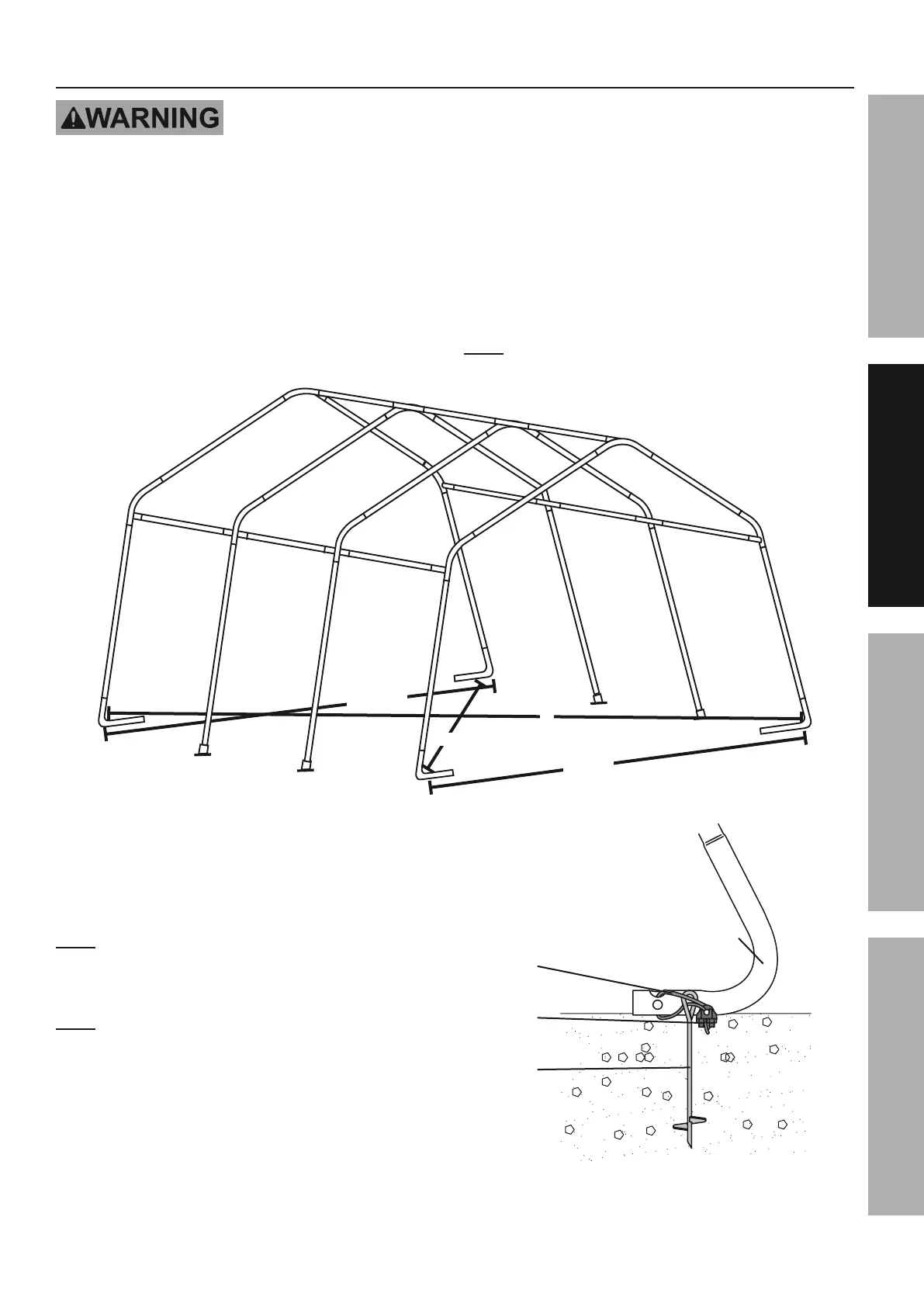
1. Position the frame in the desired installation location.
The location must be flat, level, and stable
with good locations for the Anchors (11-1).
2. Level the frame end-to-end and side-to-side.
3. Measure the width of the frame at front and back; it
should be 10′ 2" wide.
The distance diagonally in one direction should
be equal to the distance diagonally in the other
direction.
If any measurements do not match, adjust the
frame and retake measurements until they
are equal within a reasonable tolerance.
>)*"3 If measurements cannot be made correct,
then parts may not be seated together properly.
α
α
10′2"
10′2"
L$7+/"'?3''!"/$6C'2(,'<,^+.*'L/28"'H"2.+/"8"(*.
4. Once the frame is positioned, leveled, and squared,
anchor the four Corner Legs (6) as follows:
a. Thread the Anchor (11-1) into the ground near
the Corner Leg until the top of the Anchor
only extends about 3″ above the ground.
>)*"3 Verify that there are no utility lines nearby
before driving anchors. If there are rocks
or other obstacles, holes may need to be
drilled first to allow proper anchoring.
>)*"3 When anchoring frame on concrete, use
Concrete Anchor (19) in place of Anchor.
b. Insert a Cable (11-2) through the anchor
and through the Corner Leg, as shown.
c. Pull the Cable tight and secure it using a
Cable Clamp (11-3). Tighten the two nuts on
the Cable Clamp evenly to secure the Cable.
d. Repeat for all remaining Anchors
and Corner Legs.
R
OOPa
OOPb
OOPO
L$7+/"'`3''<(%#)/$(7
Page 9L)/'*"%#($%2&'M+".*$)(.N'4&"2."'%2&&'OPQQQPQRRPSTUT-Item 62859
D<L9EGJV9=<E?J>H<?>E9><>F9 D9EWV