For technical questions, please call 1-800-444-3353.
SAFETY OPERATION MAINTENANCESETUP
Maintenance and Servicing
rocedures not specifically explained in this manual must
be performed only by a qualified
REVENT SERIOUS INJURYREVENT SERIOUS INJUR
Turn the Trigger of the tool off and unplug the Adapter before performing
any inspection, maintenance, or cleaning
leaning, Maintenance, and
condition of the tool. Check for:
cracked or broken parts, and
any other condition that may
of the Spotlight with clean cloth.
Store the Adapter and tool in a dry,
indoor area out of reach of children.
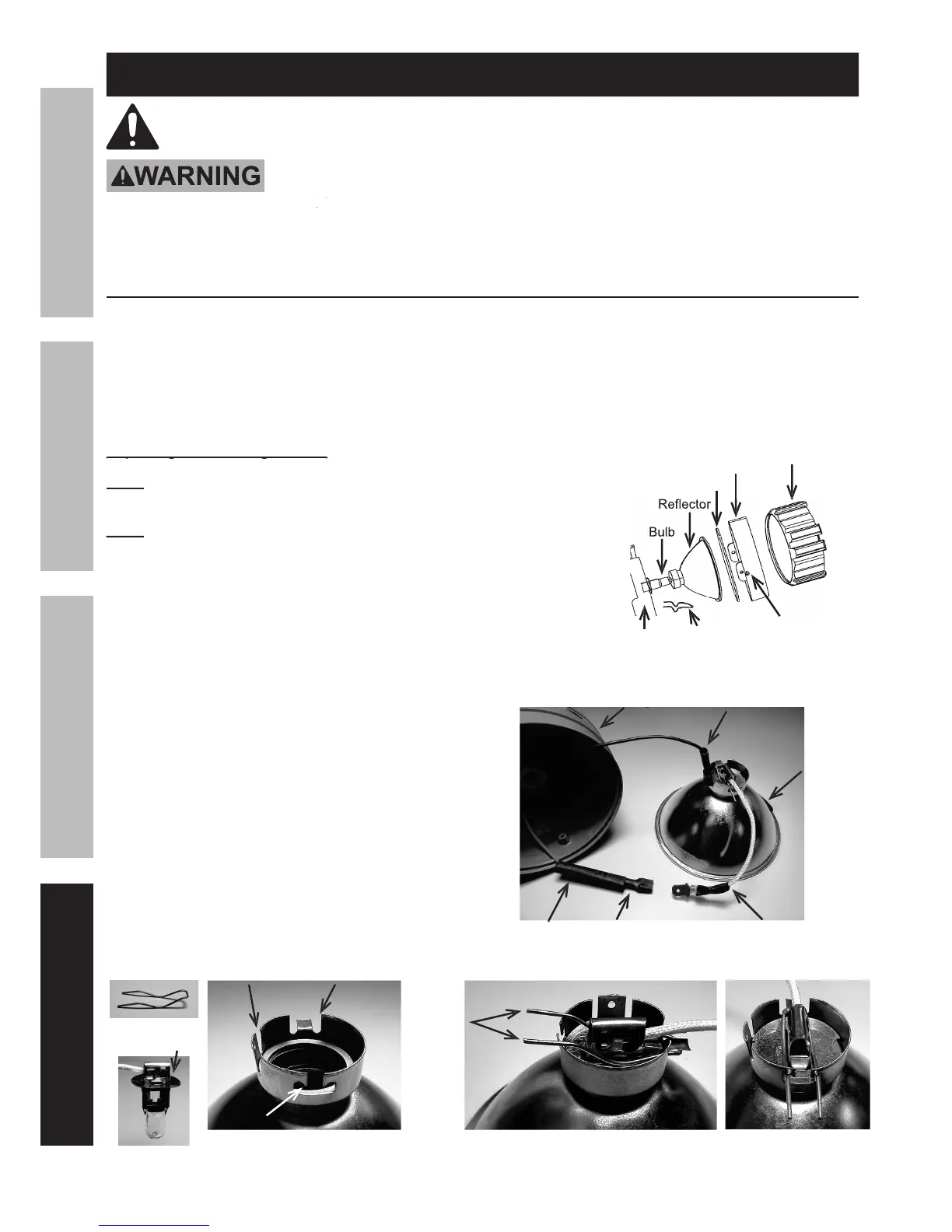
Replacing the 4V Halogen Bulb:
Replacing the 4V Halogen Bulb:
To prevent hand-oil contamination, DO NOT touch the Halogen Bulb with
bare hands. Use a lint free, soft, clean rag to handle the Bulb.
Unplug all wire connections by holding the connectors and pulling.
Unplug all wire connections by holding the connectors and pulling.
Do not pull the wires apart by tugging on the wires.
Slide the Ring Cover off of the Housing.
Unthread the two screws holding the Ring in place.
Carefully remove the Ring, the glass Lens and the Reflector.
Unplug the black wire (negative) from the bottom of the Reflector.
Pull back the casing on the red wire (positive) connection,
then unplug the bulb wire from the red wire connection.
Unhook the ends of the Spring Clip and
remove the clip and old Bulb.
Place the new Bulb into the Reflector Bowl opening
and slide the Spring clip under the Tab, over the
Bulb Flange, then lock the ends into the “T” Slot.
Plug the red and black wires back in place, sliding
the casing over the red wire connection.
Reassemble the Reflector, Lens, Ring and Ring Cover.
Bulb before locking Spring Clip in place