Do you have a question about the Hardi EVRARD ALPHA 2500 and is the answer not in the manual?
Declaration of conformity for EEC standards related to the sprayer.
Instructions for using the self-propelled sprayer for its intended purpose.
Details regarding the delivery report and its importance for warranty activation.
Identification and labeling of the main equipment and parts of the sprayer.
Essential safety precautions and warnings to be observed during operation and maintenance.
Information plates and serial number details for identifying the specific sprayer unit.
Description of the console and instrument panel mounted on the steering column.
Detailed explanation of the indicators, lamps, and switches on the steering column panel.
Identification and function of various controls and switches located on the main console.
Overview of accessories and controls within the operator's cab.
Features and adjustments related to the driver's comfort and seating.
Description of the seat's mounting, adjustments, and ergonomic features for driver comfort.
Explanation of the cab heating system and its operation using the ventilation unit.
Information on the air conditioning unit and its controls for cab climate regulation.
Information regarding the engine, including access and starting procedures.
Procedures for accessing the engine compartment for checks and maintenance.
Step-by-step guide for safely starting the engine, including pre-checks.
Description of the engine accelerator control and its function.
Procedure for safely stopping the engine and applying the parking brake.
Explanation of the controls for advancing, reversing, and braking the sprayer.
How to use the driver's control lever for forward, reverse, and neutral positions.
Details on using the engine brake for optimal drive and braking performance.
Instructions for engaging and disengaging the parking brake for safety.
Explanation of the speed selector settings for different field and road conditions.
Description of the hydrostatic wheel steering system and its modes.
Overview of the hydrostatic wheel steering system and its operational principles.
Procedure for operating the sprayer in two-wheel steering mode.
Instructions for engaging and using the four-wheel steering function.
How to operate the sprayer in crab formation for precise maneuvering.
Information and warnings regarding the spray pump and its operation.
Explanation of boom functions, including safety aspects and control operations.
Critical safety guidelines for operating boom functions, especially during movement.
Identification and function of the joystick controls for boom operation.
Procedures for unfolding and folding the "LA" aluminium boom.
Operating procedures for the "GVA" aluminium boom with variable geometry.
Details on spray section controls and foam marker operation.
Explanation of individual spray section switches and the main spray control.
Operation of the foam marker for accurate spray application guidance.
Checks and procedures for the electric circuit, including battery and lighting.
Instructions for filling the diesel tank, including safety precautions.
Procedures for checking and filling the hydraulic oil reservoir.
Key checks for the engine before starting, as per the manual.
Information on tyre pressure and wheel bolt tightening.
Preparation steps for the spray system, including nozzle fitting and filters.
Guidance on fitting the correct nozzles for the application.
Checks and maintenance procedures for suction, delivery, and in-line filters.
Checks for drain valves and the floating gauge function.
Operation and adjustment of the pneumatic circuit and filter-lubricator unit.
Explanation of the principles behind normal circulation for spraying.
Details on the normal circulation configuration for spray delivery.
Explanation of the semi-continuous circulation mode for spray application.
Description of the continuous circulation mode for spray application.
Details on various spraying stages and associated pictograms.
Explanation of pictograms used to indicate valve operations during spraying.
Schematic diagram illustrating the normal circulation circuit.
Schematic diagram illustrating the semi-continuous circulation circuit.
Schematic diagram illustrating the continuous circulation circuit.
Visual guide to manifold top positions for various spraying operations.
Procedures for operating the spraying circuit, including filling and priming.
Steps for filling the hand washing and rinsing tanks with clean water.
Procedure for priming the spray pump if it becomes empty.
Method for filling the tank using external suction.
Method for filling the tank using the main tank's contents.
Recommendations for filling the main tank before adding products.
Safety warnings and procedures for adding chemical products to the tank.
Importance and procedure for agitating the main tank contents before spraying.
Procedures for programming and executing spraying in different circulation modes.
Instructions for adjusting the radar unit for height and mode selection.
How to perform spraying operations with tank agitation enabled.
Procedure for spraying without agitation, typically with an empty tank.
Using the manual volume-regulating valve for low volume spraying.
Steps for rinsing the boom and piping to prevent chemical residue.
Procedure for transferring tank contents to another external tank.
Steps for completely emptying the main tank after rinsing.
Process for rinsing the main tank using water from the rinsing tank.
Procedure for emptying the rinsing tank for cleaning.
Emptying boom piping using air flow, specific to Clean Cut-off.
Table listing elements, capacities, and recommended lubricants.
Maintenance schedule for the initial running-in period of the sprayer.
Overview of periodic and preventive maintenance tasks based on operating hours.
Specific maintenance procedures for the DEUTZ engine.
Cleaning and replacement of the engine air filter cartridge.
Procedure for changing the engine oil and oil filter.
Steps for replacing the fuel filter and draining the pre-filter.
Procedure for venting the fuel system after maintenance or running empty.
Maintenance procedures for the fuel pre-filter.
Cleaning and draining the fuel tank.
Replacement of the safety cartridge in the air filter.
Procedures for draining and filling the engine cooling system.
Daily or hourly maintenance checks for the sprayer.
Maintenance tasks to be performed every 10 hours or daily.
Cleaning the air conditioning condenser unit.
Bleeding condensed water from the air compressed reservoir.
Maintenance checks and tasks required every 50 operating hours.
Lubrication of the diaphragm pump nipple.
Re-tightening wheel bolts and checking tyre pressure.
Greasing points on the chassis and boom components.
Lubrication and maintenance of the DG regulating valve.
Lubrication and cleaning procedures for the TVI remote valve.
Maintenance tasks to be performed every 100 operating hours.
Maintenance tasks required every 250 operating hours.
Replacement procedures for hydraulic filter cartridges.
Importance and replacement of carbon cab filters for air quality.
Maintenance of the Héliflux flowmeter, including bearing checks.
Checking and lubricating diaphragms and pistons in Pentalets.
Maintenance tasks to be performed every 500 operating hours.
Maintenance tasks required every 1000 hours or annually.
Procedure for draining and refilling the step-up gear case oil.
Maintenance of valves and diaphragms, including replacement.
Procedures for battery charging and care to ensure readiness.
Recommendations for cleaning the cab interior and roof.
Detailed steps for preparing the sprayer for off-season storage, including antifreeze.
Procedures for preparing the sprayer for the next season after storage.
Troubleshooting common faults related to the electric circuit.
Identification of fuses and relays and their locations for troubleshooting.
Diagram showing the principle wiring layout of the sprayer's electrical system.
Wiring diagram specific to the air conditioning system.
Troubleshooting common engine problems and their potential causes.
Troubleshooting issues related to the four-wheel steering system.
Troubleshooting common problems within the hydraulic circuits.
Actions to take when the hydraulic oil level alarm is activated.
Procedures and equipment needed for towing the mobile unit in case of failure.
Understanding the boom control distributor and its components.
Detailed schematic of the sprayer's hydraulic circuit.
Troubleshooting common issues encountered in the spraying circuit.
Solutions for when the spray pump fails to prime.
Causes and solutions for foam formation in the spraying circuit.
Troubleshooting issues related to the admixture of products.
Solutions for incorrect spraying, such as blocked nozzles or pressure issues.
Diagnosis and solutions for situations where spraying is not occurring.
Troubleshooting incorrect volume per hectare delivery.
Troubleshooting issues with the REGULOR control unit, including display and speed info.
Troubleshooting mechanical jamming or faults in the DG4 regulating valve.
Checks and troubleshooting for the wheel sensor.
Troubleshooting issues with the HELIFLUX flowmeter.
Troubleshooting false readings or zeroing issues with the pressure gauge.
List of main parts related to the engine.
List of main parts related to the cab.
List of main parts for the speed sensor system.
List of main parts for the steering system.
List of main parts related to fuses.
List of main parts for the pneumatic circuit.
List of main parts for the spray centrifugal pump.
List of main parts for the regulating valve.
List of main parts for the remote valve.
List of main parts for the flow meter.
List of main parts related to various valves.
Technical specifications for the engine, including power and torque.
Technical specifications for the transmission system.
Technical specifications for the sprayer's suspension system.
Technical specifications for the steering system, including turning radius.
Technical specifications related to the sprayer's track width.
Technical specifications for the parking and service brake systems.
Technical specifications related to the sprayer's cab.
Specifications for available tyre sizes and options.
Capacities of the main tank, rinsing tank, and other reservoirs.
Specifications for the electrical system components like alternator and battery.
Overall dimensions of the sprayer, including boom length and ground clearance.
Weight specifications for the sprayer in empty and full configurations.
Technical specifications for the spraying system components.
| Brand | Hardi |
|---|---|
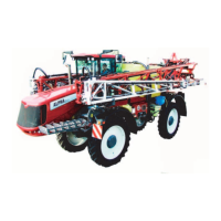
| Model | EVRARD ALPHA 2500 |
| Category | Farm Equipment |
| Language | English |