8
HARDI NAVIGATOR
6 If the wheels are reversed and exchanged, remem-
ber to tighten the wheel nuts to the specified torque -
rim plate to hub = 270 Nm / M18 or 337 Nm / M20.
7 Repeat the procedure on the right hand wheel.
8 Check the distance from the centre of the tyre to the
centre of the tank, to make sure the distance is equal
from left to right.
9 Re-tighten the axle wedges and wheel nuts to the
specified torque after 4, 8, 16, and 24 hours of work.
IMPORTANT! Always place a jack under axle and lift
the wheel to remove the load from the clamps before
tightening the clamp bolts. (Caution: Do not attempt
to jack up sprayer with full tank).
Tyres
Equal pressure in both tyres is essential. Pressure
should be kept as low as practical, i.e. baggy when the
tank is full. Check the tyre pressures against the table
below, and Load Limit table on P26.
TYRE MAX PRESSURE (kPa)
Road Work
12.4 x 46 240 145-155
18.4 x 38 240 145-155
18.4 x 30 200 145
23.1 x 30 200 145
NOTE! Sprayers fitted with controllers must always
maintain the same tyre pressure as when calibrated.
WARNING! Never inflate tyres above the manu-
facturer’s specified pressures. Over inflated tyres
can explode and cause severe personal injuries.
Connecting hydraulics
Please refer to the Boom Operator’s Manual supplied
with your sprayer documentation regarding connecting
hydraulics, boom operation, adjustment and maintenance.
Connecting electric controls
Control boxes must be fitted in the tractor cabin at a
convenient place. 12 volt power sockets are required.
The wires must have a cross-sectional area of at least
4.0 mm
2
to ensure sufficient power supply. The boxes
must be fused according to the following table.
Control Box Polarity / Wire colour Fuse (Amp)
(+) (-)
EVC operating unit Brown Blue 10
Foam marker White Black 20
Distribution valves Brown Blue 10
NOTE! Refer to the Boom Operator’s Manual supplied with
sprayer documentation re connecting boom electric controls.
For installation, operation and maintenance details for
Controllers, see the relevant Controller Operators Manual.
Emergency Operation
Refer to the troubleshooting sections of the Maintenance
Manual, Boom Operators Manual and Controller Manual.
In case of power failure check fuses (Use 1.25T Amp fuse).
It is possible to operate all functions of the operating unit
manually. First disconnect the Controller (See Controller
Operators Manual for directions), then manually turn the
emergency control knobs on the EVC units as required.
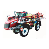
HC2500 Remote control box
Fig 12
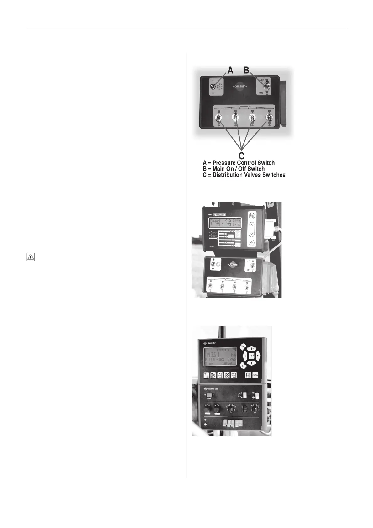
HC2500 Display and Control Box
HC5500 Display and Control Box
Fig 14
Fig 13
 Loading...