1-2 2005 PDI: All Models
NOTE
Always install/adjust handlebars before removing motorcycle
from pallet. See HANDLEBAR INSTALLATION–FLSTSC,
FLSTN AND FXDWG MODELS and ADJUSTING HANDLE-
BARS– ALL MODELS.
5. If uninstalled parts are in crate, verify your receipt of all
separate items by comparing with parts list in shipping
crate.
6. If vehicle has damage which appears to have occurred at
the factory, submit warranty claim form. Accurately
describe damage and cause. (e.g.–“Found nail in tire;
caused tire to go flat.”) Supply proper failure code(s).
1WARNING1WARNING
Do not alter or disable any device or system to circum-
vent local, state, or federal regulations. All safety and
environmental devices or systems must be left intact as
designed and built at the factory. Tampering with safety
and environmental devices or systems could result in
death or serious injury.
1WARNING1WARNING
The automatic-on headlamp feature provides increased
visibility for riders. Be sure headlamp is on at all times.
Low visibility of rider can result in death or serious
injury. (00030a).
1WARNING1WARNING
Some motorcycles are shipped with the hand brake lever
wrapped tight against the hand grip. Remove plastic
wrap and warning label (see Figure 1-4.) and pump brake
lever 3-4 times before moving motorcycle from pallet.
Failure to pump brake lever could result in an inoperable
front brake which could result in death or serious injury.
HANDLEBAR INSTALLATION–
FLSTSC, FLSTN AND FXDWG
MODELS
FLSTSC
After removing carton and protective plastic wrap:
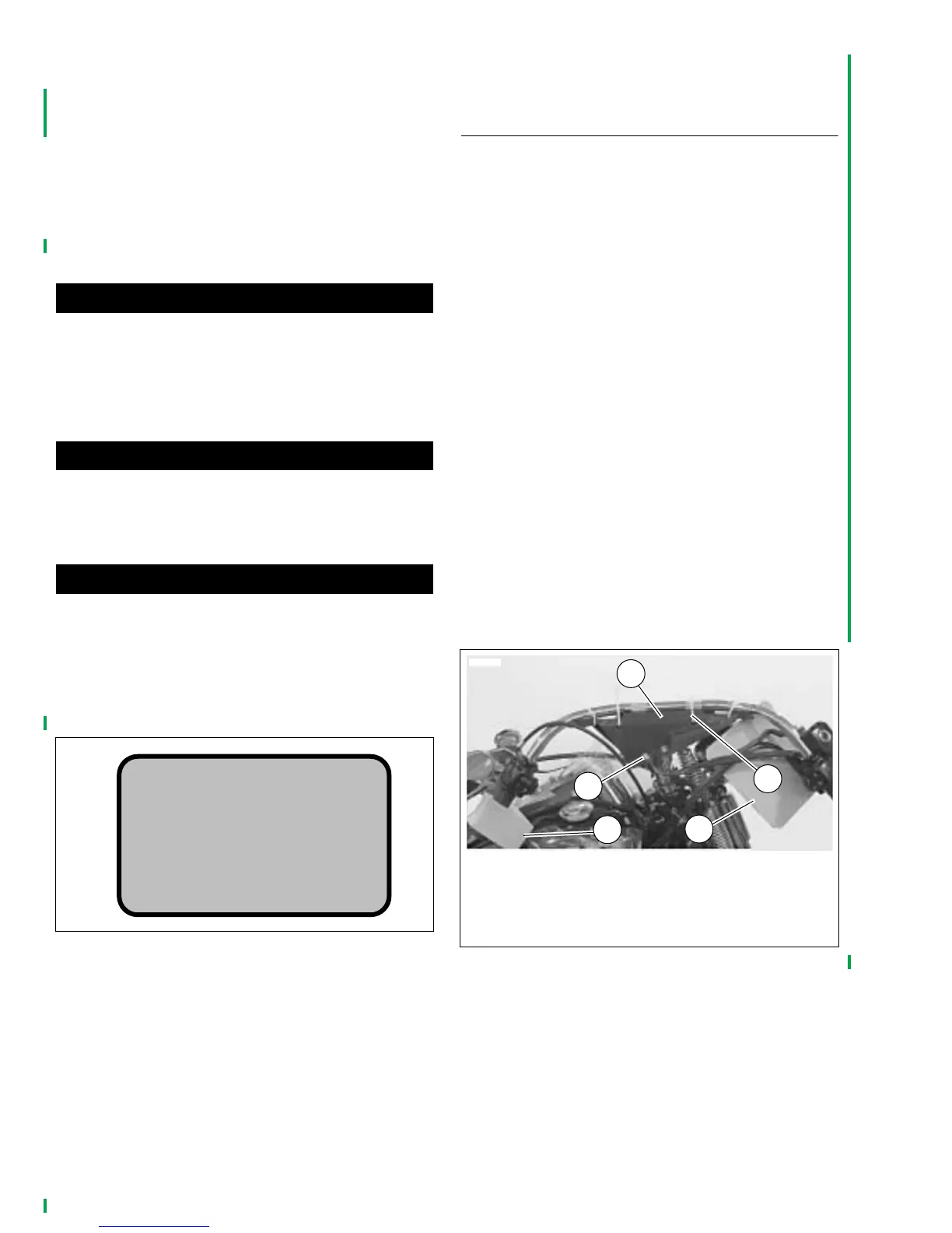
1. See Figure 1-5. While holding handlebars, remove the
riser bolts (2) securing handlebar shipping cradle (1) to
risers. Retain the four bolts, discard washers.
2. While holding the handlebar shipping cradle, cut cable
straps (3). Discard cradle and cable straps. Remove and
discard protective block (4) from left handlebar grip.
3. Route handlebar switch conduits between and behind
risers.
4. Position handlebar on top of risers, secure with riser
caps and riser bolts.
5. See ADJUSTING HANDLEBARS– ALL MODELS and
Figure 1-10. Following the Dyna Glide, Softail, XL 883,
XL 883L and XL 1200R Models procedure, adjust the
handlebars and tighten the riser bolts to 12-15 ft-lbs
(16.3-20.3 Nm) in the sequence given.
6. Push the four plastic wire retainers on the handlebar
switch conduits into the holes in the handlebars. Replace
any broken wire retainers.
7. Attach hand control and directional wire harnesses to
handlebar risers with cable straps (Part No. 10039).
8. Insert the clutch cable into the retaining clip on the left
frame downtube.
Figure 1-4. Warning Label
WARNING:
PUMP BRAKE LEVER
3-4 TIMES BEFORE
USING BRAKES
pd0171
Figure 1-5. FLSTSC
1. Handlebar shipping cradle
2. Riser bolt (4)
3. Cable strap (4)
4. Protective block
5. Protective pad
3
4
1
2
10612
5



 To Next Page