2005 PDI: All Models 1-3
FLSTN
After removing carton and protective plastic wrap:
1. See Figure 1-6. Remove and discard cloth tie (3) secur-
ing handlebar.
2. Remove the riser bolts (2) and shipping clamp (1) from
handlebar risers. Retain the bolts. Remove and discard
protective block (4) from right handlebar grip.
3. Route handlebar switch conduits between and behind
risers.
4. Position handlebar on top of the risers and secure with
riser caps, and bolts removed in step 2.
5. See ADJUSTING HANDLEBARS– ALL MODELS and
Figure 1-10. Following the Dyna Glide, Softail, XL 883,
XL 883L and XL 1200R Models procedure, adjust the
handlebars and tighten the riser bolts to 12-15 ft-lbs
(16.3-20.3 Nm) in the sequence given.
6. Push the four plastic wire retainers on the handlebar
switch conduits into the holes in the handlebars. Replace
any broken wire retainers.
7. Insert the clutch cable into the retaining clip on the left
frame downtube.
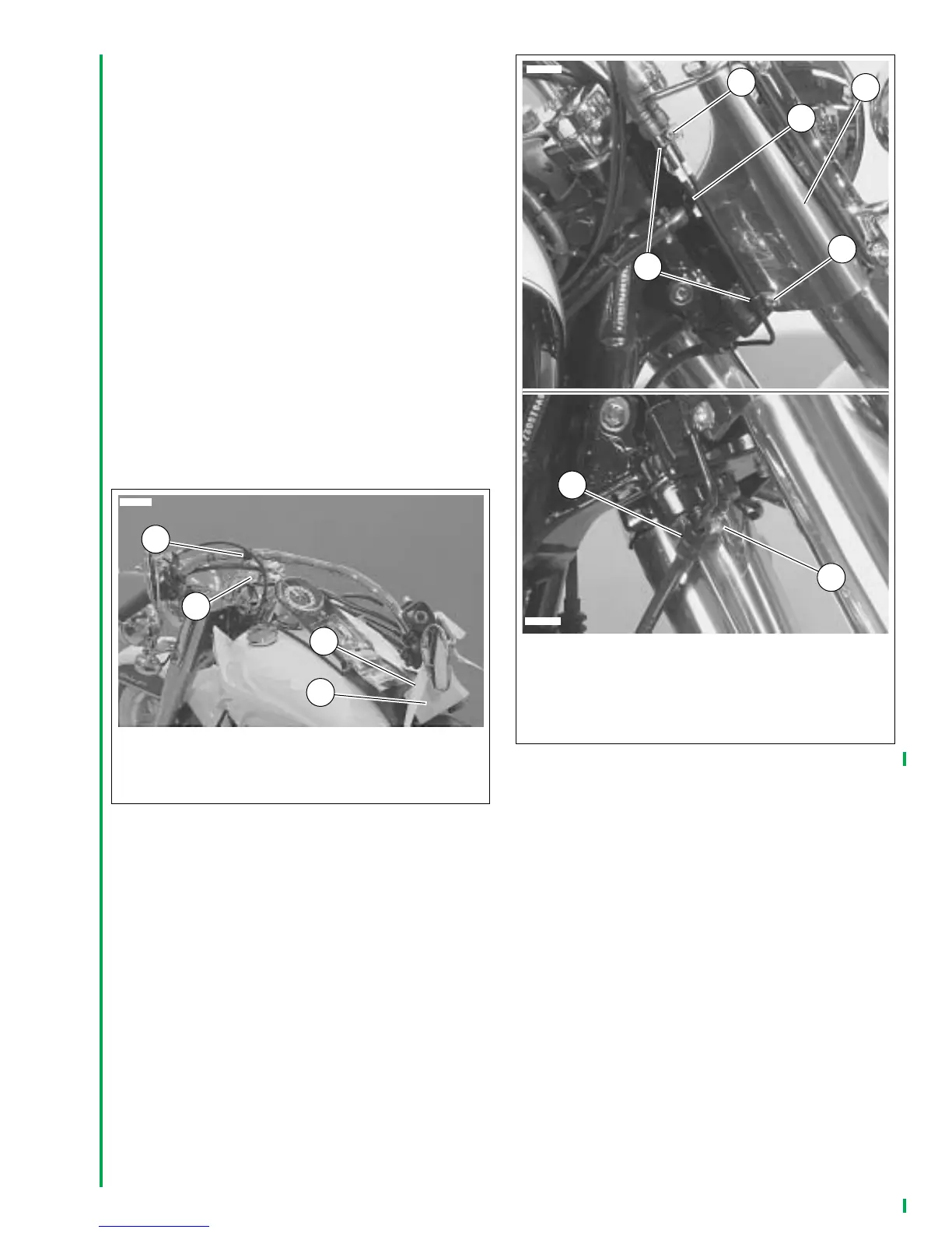
8. See Figure 1-7. Install front brake line (1) in clamps (2),
inboard of screws (3) and attach to fork stem cover (4).
Tighten screws to 30-50
in-lbs
(3.4-5.7 Nm).
9. Install brake line in clamp (5) in underside of lower fork
clamp. Tighten screw (6) to 96-120
in-lbs
(10.9-13.6
Nm).
Figure 1-6. FLSTN
1. Shipping clamp
2. Riser bolts
3. Cloth tie
4. Protective block
3
1
2
10613
4
Figure 1-7. Attaching Front Brake Line–FLSTN
1. Front brake line
2. Clamp (2)
3. Screw (2)
4. Fork stem cover
5. Clamp
6. Screw
1
6
2
10614
3
5
3
4
10615
 Loading...