2005 PDI: CVO Models 7-1
VRSCSE MODEL 7.1
GENERAL
Follow the instructions in section I (All Models) and Section VI
(VRSC Models) and the following instructions to perform the
predelivery setup procedure on the VRSCSE model.
This motorcycle is equipped with the Harley-Davidson Fac-
tory Security System and siren.
UNCRATING
The VRSCSE is shipped in a “turn-wheel” crate which allows
the handlebar to be shipped in position on the handlebar ris-
ers.
Remove foam block from left handlebar grip. Remove plastic
end caps from both handlebar grips. Discard foam block and
plastic end caps.
Check Contents of Crate
Check that the following items are in a box in the crate:
● Motorcycle cover inside a storage bag
● Owner’s kit
● Two mirror kits
● CVO ignition key
NOTE
If any parts are missing, call 1-800-695-2925 or Fax 1-717-
852-6717. Provide your Dealer name, number, person to con-
tact, part number of missing item, and Motorcycle VIN.
BATTERY TESTING AND CHARGING
Batteries contain sulfuric acid, which could cause severe
burns to eyes and skin. Wear a protective face shield,
rubberized gloves and protective clothing when working
with batteries. KEEP BATTERIES AWAY FROM CHIL-
DREN. (00063a)
Never remove warning label attached to top of battery.
Failure to read and understand all precautions in warning
could result in death or serious injury. (00064a)
Battery posts, terminals and related accessories contain
lead and lead components, chemicals known in the State
of California to cause cancer and birth defects or other
reproductive harm. Wash hands after handling. (00019a)
NOTES
● The engine is equipped with a compression release, so a
smaller (12 amp hour) battery provides adequate starting
current.
● It will be necessary to remove the airbox cover to gain
access to the battery.
Removing Airbox Cover
1. Unlock and open seat.
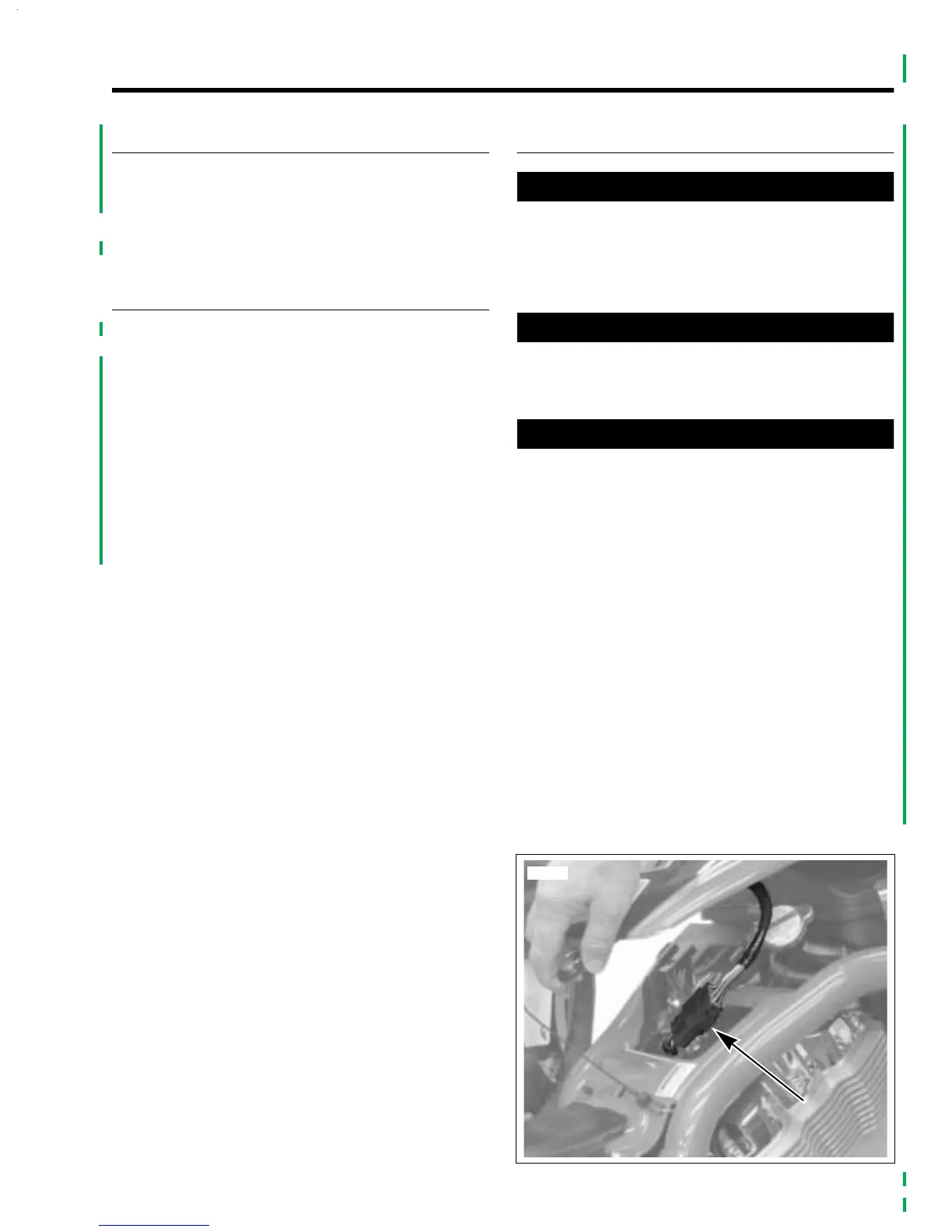
2. See Figure 7-1. Unlatch and lift rear of airbox cover a few
inches.
3. Disconnect console connector.
4. Carefully slide airbox cover back to disengage locating
pins at front of cover from mounting tabs on frame.
Remove cover.
Figure 7-1. Console Connector
1