7-2 2005 PDI: CVO Models
Testing and Charging Battery
1. Place test probes of voltmeter on battery terminals and
check the voltage of the battery to make sure it is at least
12.6 VDC.
2. If the open circuit (disconnected) voltage reading is 12.6
VDC or greater the battery is ready for use.
3. See Section 1. Mark the date on the battery warranty tag
by removing the applicable month and year. Month and
year punches may be removed with the point of a screw-
driver without removing battery.
4. If the open circuit (disconnected) voltage reading is
below 12.6 VDC, refer to Table 1-2, 12 amp-hour battery,
in Section 1 and charge battery at rate and time speci-
fied.
5. Recheck battery voltage by repeating step 1 above. If
voltage now is 12 VDC or greater, perform steps 2 and 3
above.
6. If the open circuit (disconnected) voltage reading is still
below 12.6 VDC, the battery must be replaced. To
remove battery, air cleaner and air cleaner bottom
must be removed. See appropriate Service Manual for
procedure.
IMPORTANT NOTE
Only remove air cleaner and air cleaner bottom if battery
could not be charged to 12.6 VDC and battery must be
removed and replaced.
Installing Airbox Cover
1. Carefully install airbox cover over airbox. Be careful not
to scratch or damage airbox cover, console or speedom-
eter. Engage locating pins on front of airbox cover with
tabs on frame.
2. See Figure 7-1. Connect console connector halves
together.
3. Lower rear of airbox cover onto frame and latch in place.
4. Close and lock seat.
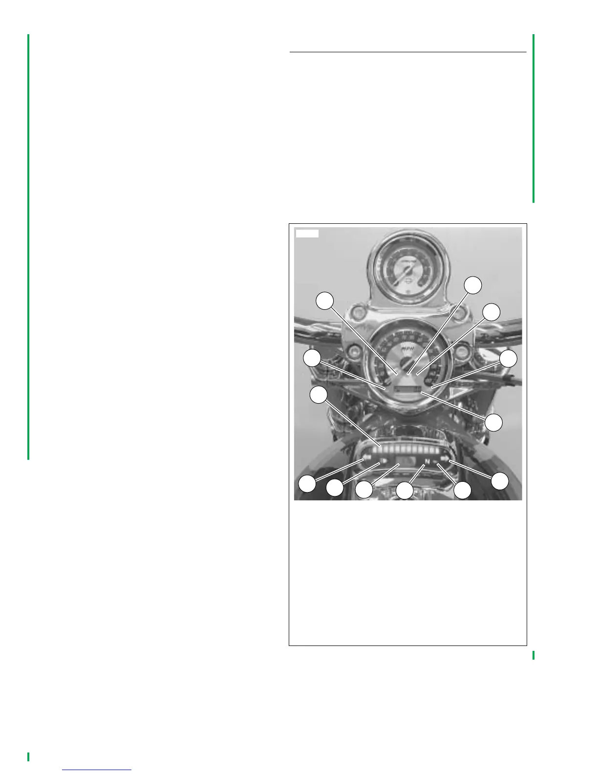
INDICATOR LAMPS AND DISPLAYS
1. See Figure 7-2. View indicator lamps and displays and
turn ignition switch to “IGNITION” position. Check that
the oil pressure indicator lamp (12) turns on (before
engine is started). The Check Engine indicator lamp (2)
will illuminate for about four seconds and then go off. The
security lamp (5) will illuminate for about four seconds
and then go off. The Battery icon (4) will illuminate to
indicate low voltage. Fuel gauge (7) should also indicate
fuel tank level. Engine Coolant temperature lamp (1) will
illuminate to verify bulb filament and then go off.
NOTE
For any systems problems, please refer to the appropriate
Electrical Diagnostic manual for your model.
Figure 7-2. VRSCSE Indicator Lamps and Displays
1. Engine coolant temperature
2. Check engine
3. Low fuel
4. Alternator
5. Security system
6. Odometer/trip odometer
7. Fuel gauge
8. Left turn signal
9. High beam
10. Clock
11. Neutral
12. Oil
13. Right turn signal
10771
3
4
5
2
1
6
7
8
9
10
11
12
13