7-12 2005 PDI: CVO Models
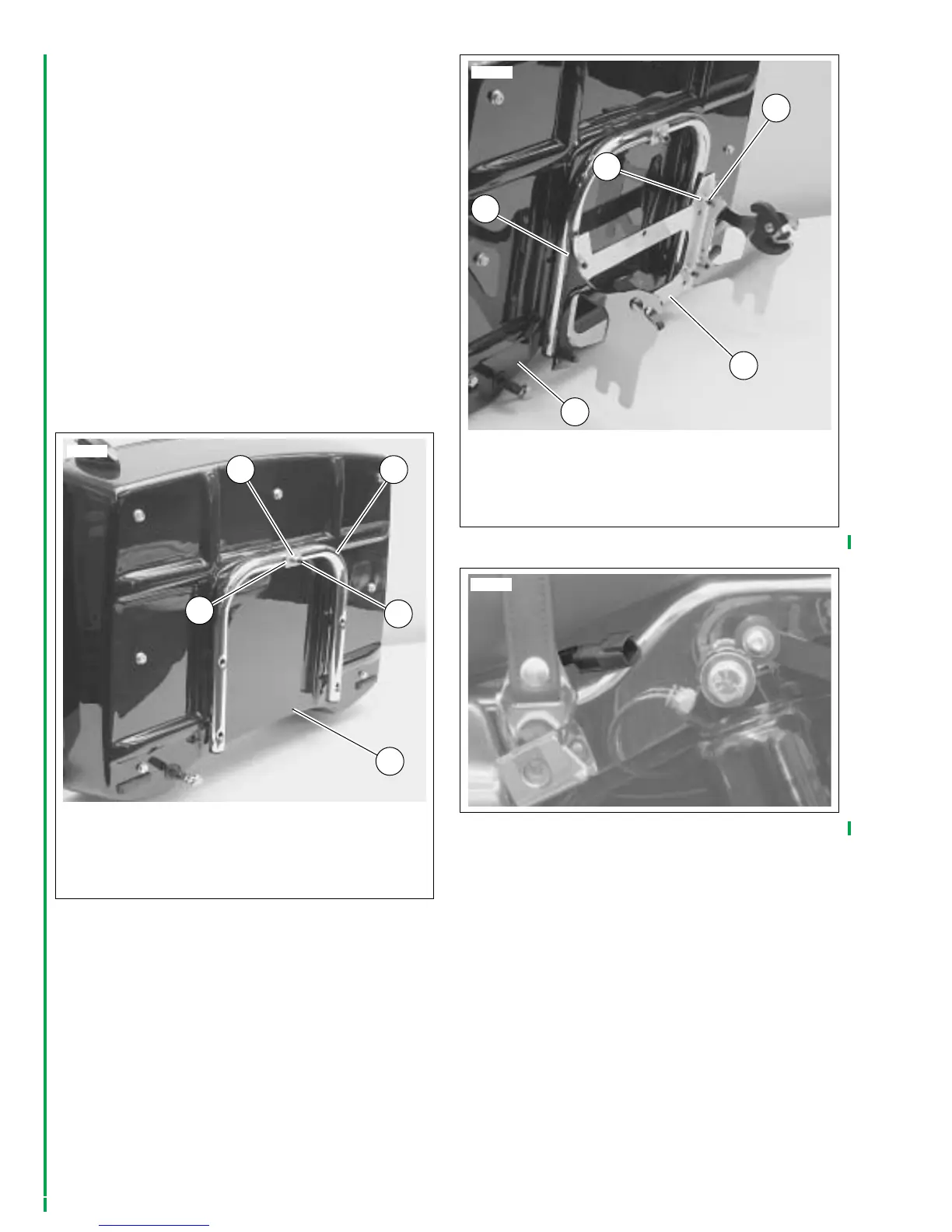
5. See Figure 7-18. Insert one screw with washer through
rear-most hole in Tour-Pak. Slide support tube onto
screw.
6. Install one saddle spacer onto screw with curved surface
of spacer facing support tube. Install washer and locknut.
Finger-tighten locknut only.
7. Install screws and washers in other four locations,
through Tour-Pak and support tube. Install saddle spac-
ers on screws with curved surface of each spacer facing
support tube.
8. See Figure 7-19. Slide removable mounting bracket (1)
onto screws with bracket latches facing rear of Tour-Pak.
9. Install washers and locknuts (2, 3). Tighten all five
screws and locknuts to 96-120 in-lbs (10.8-13.5 Nm).
10. See Figure 7-13. Install Tour-Pak on Tour-Pak bracket
mounts (1) and lock latches in place.
11. See Figure 7-20. Locate Tour-Pak power connector
between seat and fender strut cover on left side of motor-
cycle.
Figure 7-18. Mounting Support Tube
10705
1. Support tube
2. Saddle spacer
3. Screw and locknut
4. Washer
5. Tour-Pak (front surface facing down)
1
3
2
5
4
Figure 7-19. Removable Mounting Bracket
Figure 7-20. Tour-Pak Power Connector
10768
1. Removable mounting bracket
2. Screw and locknut (4)
3. Washer (4)
4. Saddle spacer (4)
5. Tour-Pak (front surface facing down)
1
2
3
4
5
10688



 To Next Page