2005 PDI: All Models 1-9
VRSCB
NOTE
To gain access to the handlebar adjusting screws, the follow-
ing steps will be necessary:
1. Remove Maxi-Fuse.
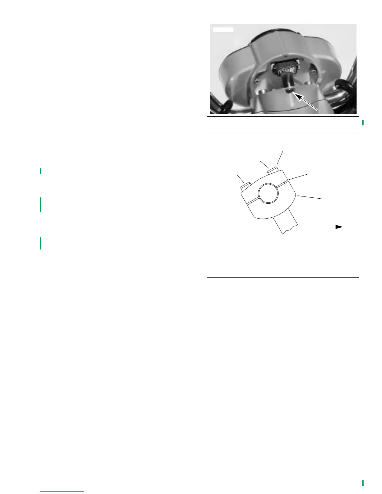
2. See Figure 1-16. Remove instrument cluster screw from
location shown and pivot instrument cluster away from
handlebars.
3. Remove wiring harness connector and remove screw on
bottom side of instrument cluster.
4. Remove instrument cluster.
5. To be sure handlebars are properly centered, verify that
equal amounts of knurled areas on handlebar protrude
from outboard sides of upper handlebar clamp.
NOTE
On some models, knurled areas of handlebar will be com-
pletely hidden by upper handlebar clamp and will not be visi-
ble at all when handlebar is centered properly.
6. See Figure 1-17. Raise handlebars to normal riding posi-
tion; hold in position. Tighten two front screws (4) until
cast-in spacers (2) of upper clamp contact handlebar
lower clamp (1).
7. Tighten rear screws (3) to 16-20 Nm (12-15 ft-lbs).
8. Final tighten front screws (4) to 16-20 Nm (12-15 ft-lbs).
Slight gap between upper and lower clamps should exist
at rear.
9. Install instrument cluster.
10. Insert instrument cluster screw and tighten to 2.2-2.8 Nm
(20-24
in-lbs
).
11. Install Maxi-Fuse.
Figure 1-16. Instrument Cluster Mounting Screw Location
Figure 1-17. VRSCB Models
1. Lower clamp
2. Cast-in spacers (2)
3. Rear screw (2)
4. Front screw (2)
5. Upper clamp
pd0021b
3
2
5
Tighten
first
FRONT
1
4