2005 PDI: Touring Models 2-3
INSTALLING DATA LINK
CONNECTOR
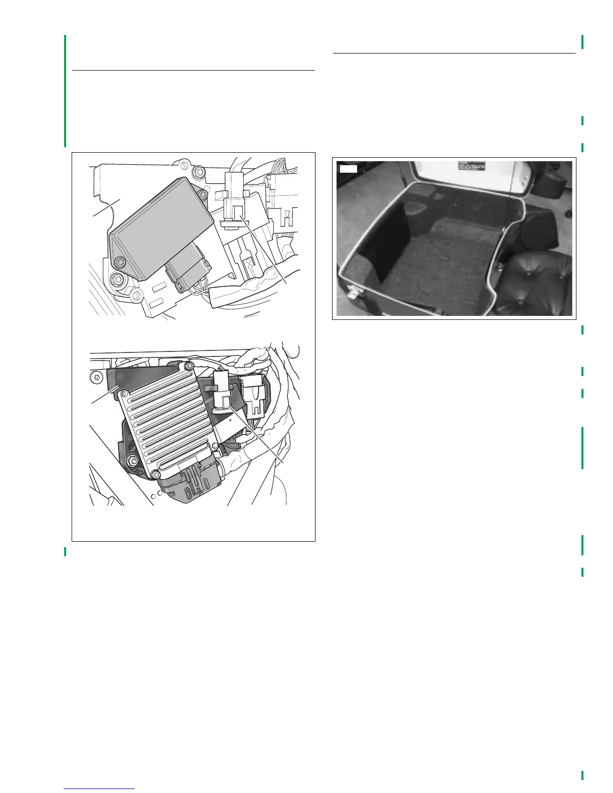
See Figure 2-1. The data link connector [91] (2) mounts in a
clip on the electrical bracket (1) under the right side cover.
Cut the cable tie securing the data link connector harness to
the frame and snap the connector into its clip on the electrical
bracket.
INSTALLING TOUR-PAK
®
NOTE
The seat screw is not factory installed on models with Tour-
Paks. The seat screw is in the Parts Kit, Part No. 53318-99.
On Ultra models, see Figure 2-2. Remove map pouch and
molded Tour-Pak liner from Tour-Pak prior to performing the
following procedures. Install both after work is completed.
Five Bolt Mounting
Note that Tour-Pak has seven mounting holes which allow it
to be positioned forward on luggage rack for shipping
only. Mount Tour-Pak in the rearward position (front four
holes and rear center hole) so seat access screw can be
reached.
1. To avoid dropping or scratching the Tour-Pak, disconnect
the radio antenna cable and Tour-Pak lights connectors
and feed wiring out through hole at front of Tour-Pak
(after removing grommet). On Ultra models, repeat the
procedure to release the CB antenna cable and connec-
tor.
2. If not already removed, remove seat.
3. Place a protective blanket across the frame tubes in the
seat area.
4. From inside Tour-Pak, remove the nuts and oversized
shipping washers and then lift the Tour-Pak off the
mounting bolts setting it on the blanket. Retain nuts for
use later, discard large shipping washers.
Figure 2-1. Data Link Connector
1. Electrical bracket
2. Data link connector [91]
pd0215
Carbureted
Fuel injected
1
1
2
2
pd0216
Figure 2-2. Tour-Pak Liner and Map Pouch