2-4 2005 PDI: Touring Models
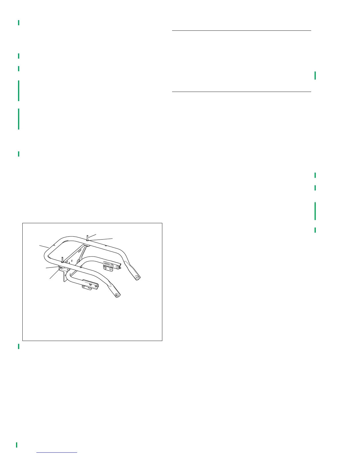
5. See Figure 2-3. Remove and discard the pushnuts (5)
from the mounting bolts (1), and pull the bolts (1) and
washers (2) from the luggage rack (although the spacers
(4) may be left in place between the top support tube (3)
and the license plate bracket).
6. Locate Parts kit, Part no. 53318-99 in Tour-Pak or sad-
dlebag. The plastic bag contains three spacers, bolts,
nuts and five washers used to mount Tour-Pak. Also in
parts kit is the seat retaining screw.
7. See Figure 2-4. Move Tour-Pak to rear so five mounting
holes align with five holes in top support tube.
NOTE
Make certain bolts are installed with threaded end down. Bolt
head and washer must be inside Tour-Pak.
8. From inside Tour-Pak, install right rear bolt (1) and
washer (2) through bottom of Tour-Pak, hole in top sup-
port tube (3), luggage rack spacer (4), and hole in
license plate bracket (5).
9. Install washer (2) and locknut (6) on right rear bolt and
tighten “finger-tight”. (This fastener will keep Tour-Pak in
position while remaining four bolts are installed.)
10. Install antenna ground lead ring terminal under washer
of rear mounting bolt and install rear bolt as shown in
Figure 2-4.
11. Install remaining bolts, washers, spacers and nuts as
shown in Figure 2-4.
12. Tighten five nuts and bolts to 96-120 in-lbs (10.8-13.5
Nm).
SEATS AND PASSENGER STRAP
Refer to Touring Models Owner’s Manual for seat and pas-
senger strap removal and installation instructions. Road Glide
models must have the seat strap installed per the appropriate
Service Manual.
INSTALLING SIDECOVERS AND
SADDLEBAGS
Check that each saddlebag is firmly seated on its saddlebag
bottom support rail. Check that adequate clearance exists
between saddlebags and sidecovers. The front and rear
mounting brackets of each saddlebag have slotted mounting
holes (on the bracket ends which attach to the motorcycle) to
allow for vertical adjustment of the saddlebag. If adjustment is
necessary, loosen the bolts which secure the saddlebag
mounting brackets to the motorcycle. Press down and to the
rear firmly on closed saddlebag, and then tighten the bolts to
60-96 in-lbs (6.8-10.8 Nm) torque.
NOTE
It is essential that the Tour-Pak be installed in the rearward
position or seat removal/installation will not be possible due to
interference with the forward-mounted Tour-Pak.
On Ultra models, see Figure 2-5. Check that AM/FM/WB
antenna (left side) cable is in its two clips on left side of Tour-
Pak floor. Also check that CB antenna (right side) cable is in
two clips on right side of Tour-Pak floor. Verify that ground
strap of AM/FM/WB antenna is securely fastened to base
plate in Tour-Pak with rear mounting screw.
Figure 2-3. Tour-Pak Shipping Fasteners
1. Bolt, 1/4-20 x 2-1/4 in. (2)
2. Washer 1/4 in. inside dia. (2) (under bolt head)
3. Top support tube
4. Luggage rack spacer (2)
5. Pushnuts (2)
1
2
3
4
5
pd0188