2005 PDI: Touring Models 2-15
EVAPORATIVE EMISSIONS
CONTROL SYSTEM–CALIFORNIA
MODELS ONLY
See Figure 2-18. See Figure 2-19. Verify correct evaporative
emissions control system hose routing, connections, and fuel
tank venting to canister (if equipped).
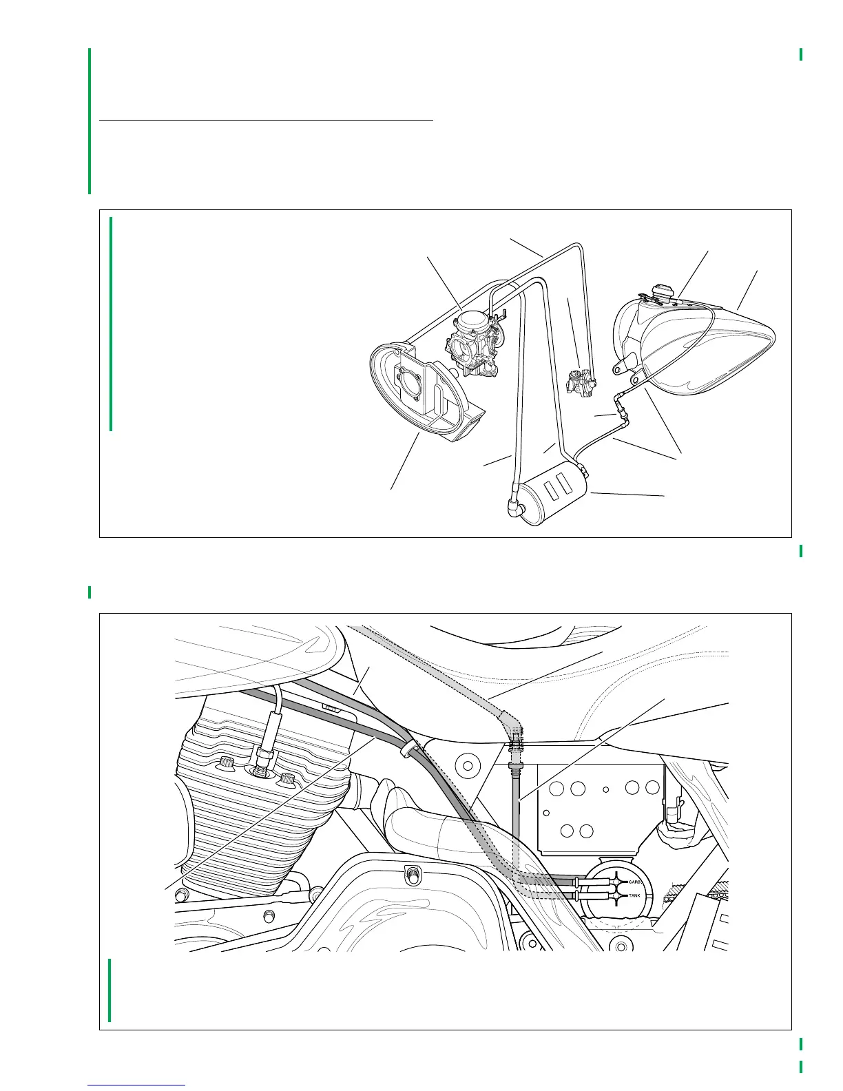
Figure 2-18. Evaporative Emissions Control System Hose Connections
1. Carburetor (induction module on
fuel-injected models)
2. Vacuum tube
3. Fuel valve
4. Filler neck fitting (Top of canopy on
FLHR/C/S)
5. Fuel tank
6. Fuel vapor vent tube
7. Vapor valve
8. Charcoal canister
9. Purge tube
10. Clean air inlet tube (not used on
fuel-injected models)
11. Air cleaner backplate
3
8
7
4
2
1
9
6
5
10
11
f1706x4x
Figure 2-19. Evaporative Emissions Control System Hose Routing
1. Clean air inlet tube from air cleaner backplate (carbureted models only)
2. Purge tube to carburetor or induction module
3. Fuel vapor vent tube from fuel tank
4. Fuel vapor vent tube from vapor valve
3
4
2
1
f1884x4x