2005 PDI: Touring Models 2-17
INDICATOR LAMPS/CONTROLS
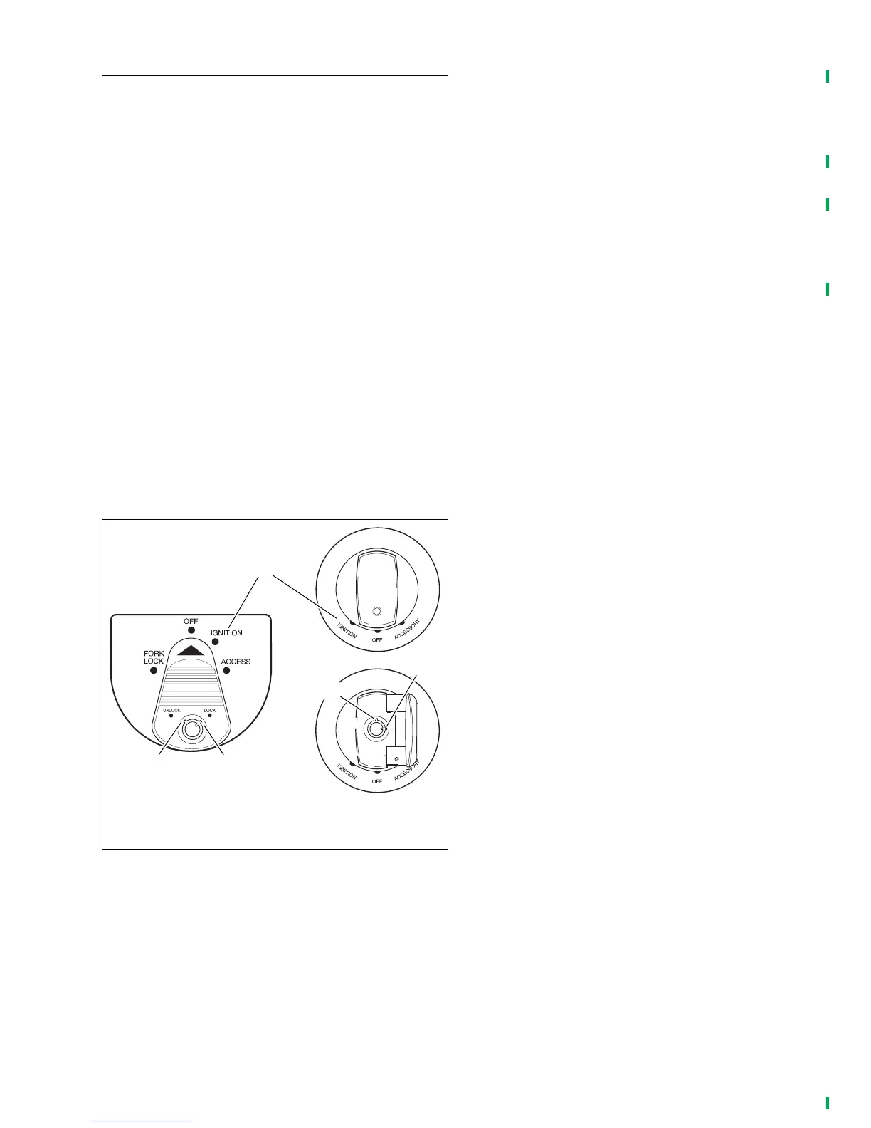
1. See Figure 2-21. Tu rn ignition/light switch to IGNITION
position, and check that Oil pressure indicator lamp turns
on (before engine is started). The Check Engine lamp
and if TSSM EQUIPPED, THE SECURITY LAMP will illu-
minate for approximately four seconds and then turn off.
NOTES
For any Systems problems, refer to the appropriate Electrical
Diagnostic manual for your model.
2. Shift transmission to neutral position, and verify that neu-
tral indicator lamp turns on.
3. Start engine; check operation of starter.
NOTE
On Police models, the clutch lever must be depressed to
operate the starter.
4. Check that oil pressure indicator lamp turns off when
engine is running above 1000 RPM.
5. Check operation of tachometer (if equipped).
6. Disengage clutch (depress clutch lever), and verify that
neutral indicator lamp turns off when transmission is
shifted to any forward gear. Shift transmission to neutral
position, and verify that neutral indicator lamp turns on
again.
7. Check horn operation.
8. Check operation of all remaining lamps:
● Headlamp–low and high beams
● Headlamp high beam indicator lamp
● Passing/pursuit lamps
● Pursuit lamp indicator lamp (FLHTP)
● Left directional (turn signal) lamps–front and rear
● Left directional (turn signal) indicator lamp
● Right directional (turn signal) lamps–front and rear
● Right directional (turn signal) indicator lamp
● Left front running lamp
● Right front running lamp
● Tail lamp–running lamp and brake lamp filaments
● Speedometer illumination lamp
● Tachometer illumination lamp (if equipped)
● License plate lamp (HDI only)
● Sound System Operation (if equipped)
9. After engine has reached normal operating temperature,
turn engine off.
10. Check engine oil level in manner previously specified.
This time, fill oil tank to upper mark on filler cap/dipstick.
Figure 2-21. Ignition Switches
pd0192
1. Ignition switch unlocked
2. Ignition switch locked
3. “Key ON” Ignition position
1
2
2
1
3