5-2 2005 PDI: Sportster Models
INITIAL ASSEMBLY 5.2
BATTERY TESTING AND CHARGING
1WARNING1WARNING
Batteries contain sulfuric acid, which could cause severe
burns to eyes and skin. Wear a protective face shield,
rubberized gloves and protective clothing when working
with batteries. KEEP BATTERIES AWAY FROM CHIL-
DREN. (00063a)
1WARNING1WARNING
Never remove warning label attached to top of battery.
Failure to read and understand all precautions in warning
could result in death or serious injury. (00064a)
1WARNING1WARNING
Battery posts, terminals and related accessories contain
lead and lead components, chemicals known in the State
of California to cause cancer and birth defects or other
reproductive harm. Wash hands after handling. (00019a)
1. Grasp left side cover at upper corners and gently pull
away from plastic mounting clips on frame.
2. Lift cover up slightly so mounting grommet clears mount-
ing tab on battery tray. Remove cover.
3. Place test probes of voltmeter on battery terminals and
check the voltage of the battery to make sure it is at least
12.6 VDC.
4. If the open circuit (disconnected) voltage reading is 12.6
VDC or greater the battery is ready for use.
5. See Section 1. Mark the date on the battery warranty tag
by removing the applicable month and year. Month and
year punches may be removed with the point of a screw-
driver without removing battery.
6. If the open circuit (disconnected) voltage reading is
below 12.6 VDC, refer to Table 1-2, 12 amp-hour battery,
in Section 1 and charge battery at rate and time speci-
fied.
7. Recheck battery voltage by repeating step 2 above. If
voltage now is 12 VDC or greater, perform steps 2 and 3
above.
8. If the open circuit (disconnected) voltage reading is still
below 12.6 VDC, the battery must be replaced.
9. Place bottom of side cover with grommet onto mounting
tab on battery tray.
10. Line up top of side cover with mounting clips aligning
with front clip first. Press top of side cover into clips until
snug.
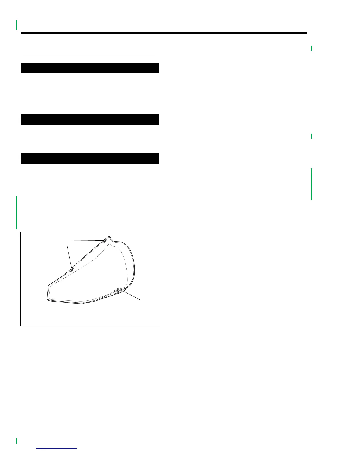
Figure 5-1. Left Side Cover
x0628x1x
1. Mounting slots (top)
2. Mounting grommet (bottom)
2
1