3. If decal on outside housing is removed, scrape remaining
adhesive from surface with a razor blade.
4. Inspect brake pads and brake disc. See 1.16 BRAKE
PADS AND DISCS.
ASSEMBLY
NOTE
Do not use D.O.T. 4 brake fluid for lubrication. Use of D.O.T.
4 brake fluid will result in increased lever travel.
1. Lubricate the following parts prior to assembly using a
light coat of G.E. VERSILUBE® #G322 L SILICONE
GREASE (marked "Piston Lube") from the service parts
kit. All other surfaces must be dry for assembly.
a. Lubricate nose radius and outside diameter of piston.
Apply lube to inside of caliper piston bores.
b. Apply lube to inside diameter of seals and wipers.
Avoid leakage. Prevent damage to piston or piston bore.
Use non-metallic tools when servicing components.
(00529d)
2. See Figure 2-67. Install a new square seal (3) and a new
wiper (4) into each piston bore. Use a wooden toothpick
(2) to aid installation if needed.
3. See Figure 2-71. Install pad spring (2) in each piston.
Ensure spring is securely installed in the groove in the
piston.
4. Turn the piston so the pad spring (2) is oriented as shown.
Carefully insert pistons, by hand, into bores of both caliper
housings. Press pistons squarely into place until they
bottom in the bores. If installation shows resistance,
remove piston and check that seals and wipers are prop-
erly installed.
5. Place a new crossover seal (1) on inside caliper housing.
6. Assemble caliper housings.
a. Install bleeder valve and tighten to 80-100 in-lbs (9.0-
11.3 Nm).
b. Verify that new crossover seal is installed on inside
caliper housing.
c. See Figure 2-67. Mate inside and outside caliper
housings using bridge bolt (11) and upper mounting
bolt (long) (13) (metric).
d. Tighten bridge bolt to 28-38 ft-lbs (38.0-51.5 Nm).
Always replace brake pads in complete sets for correct
and safe brake operation. Improper brake operation could
result in death or serious injury. (00111a)
NOTES
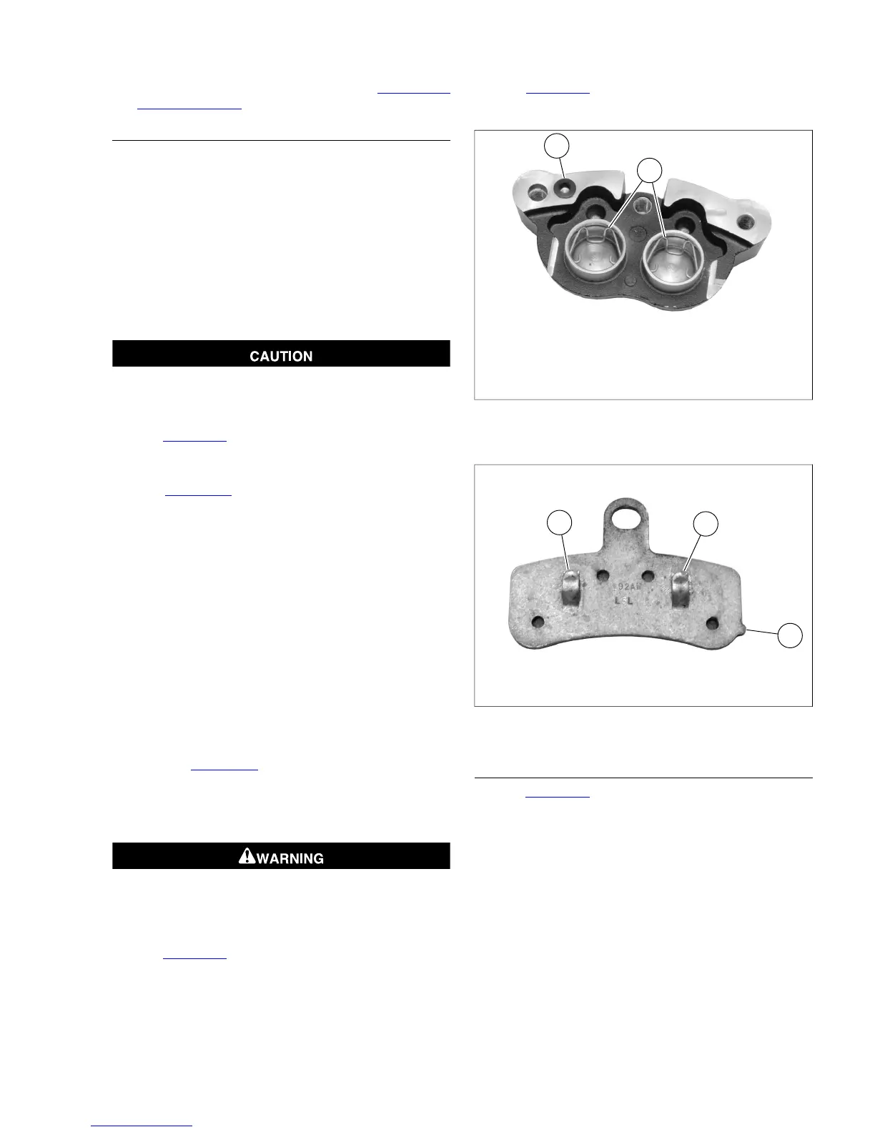
• See Figure 2-72. Ensure the pad spring tabs (1) on brake
pad engage the pad springs in the pistons.
• If the directional tab (2) does not face down when caliper
is installed, brake noise may develop.
7. Install new pads into caliper. The directional tab (2) must
face down when caliper is installed.
8. See Figure 2-67. Install pad pin/bridge bolt (12) (metric).
Tighten to 15-16 ft-lbs (20.3-22.6 Nm).
1. Pad spring tabs
2. Directional tab
Figure 2-72. Front Brake Pad
INSTALLATION
1. See Figure 2-73. Attach caliper to fork leg.
a. Place caliper over brake disc with bleeder valve facing
upwards.
b. Loosely install long mounting bolt (4) (metric) into top
hole on fork leg.
c. Install short mounting bolt (5) (metric) into bottom hole
on fork leg. Tighten bottom mounting bolt to 28-38 ft-
lbs (38.0-51.5 Nm).
d. Final tighten the top mounting bolt to 28-38 ft-
lbs (38.0-51.5 Nm).
2008 Dyna Service: Chassis 2-39



 To Next Page