2.21THROTTLE CONTROL
REMOVAL/DISASSEMBLY
1. See Figure 2-94. Loosen cable adjuster jam nuts. Screw
throttle cable adjuster until it is a short as possible.
Remove the two screws that hold the handlebar housing
together to separate the upper and lower housings.
2. Unhook the ferrules and cables from the throttle grip and
lower housing.
3. Remove air cleaner assembly and disconnect throttle
cables from induction module. See 4.4 AIR CLEANER
ASSEMBLY, Removal.
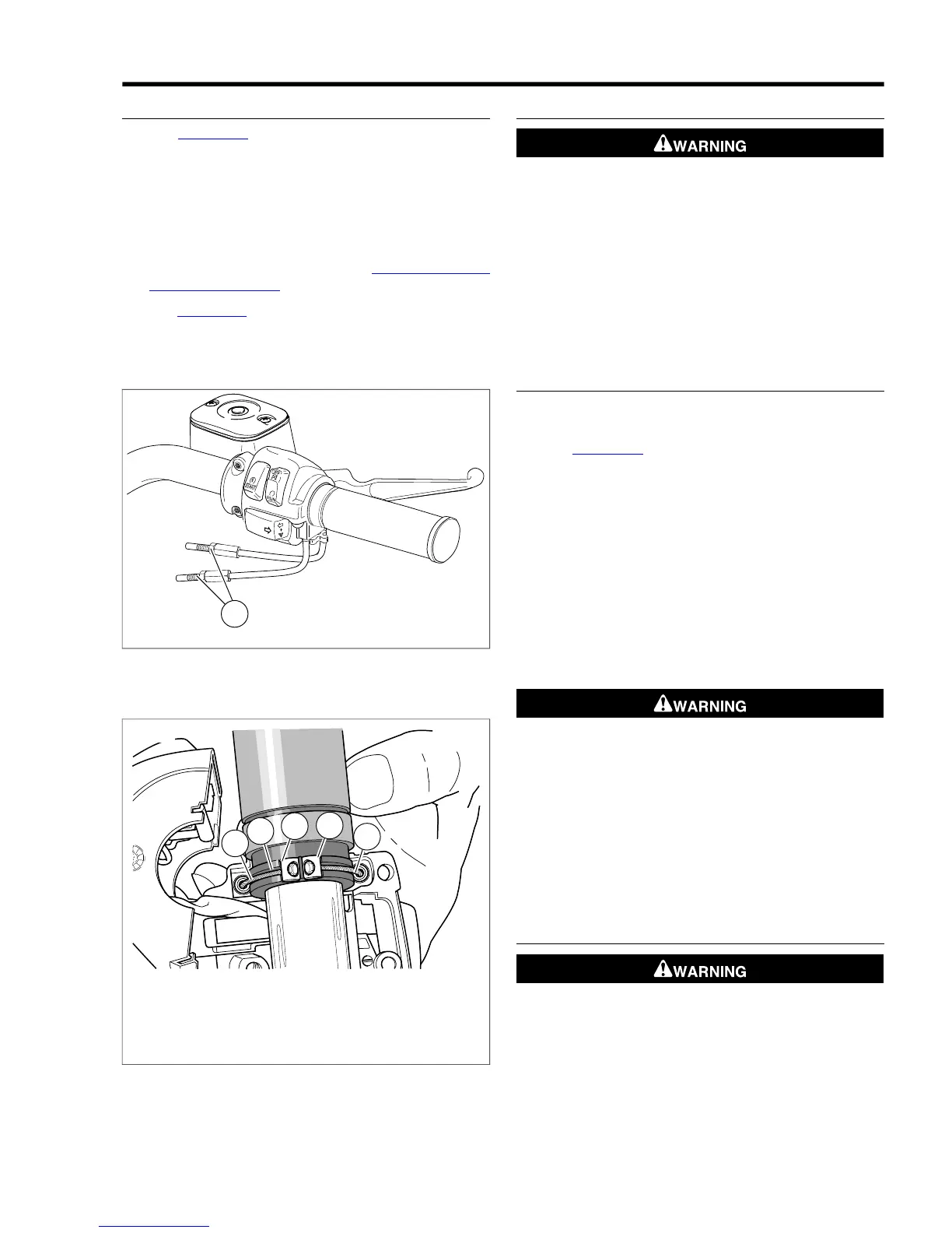
4. See Figure 2-95. Pull the cables from the housing by pla-
cing a drop of oil on the retaining ring that holds the cable
in the housing, then firmly pull the bent tubing portion of
the cable out of the housing using a rocking motion.
1. Throttle cable (silver insert, front hole)
2. Groove in throttle grip
3. Notch
4. Brass ferrule
5. Idle cable (gold insert, rear hole)
Figure 2-95.Throttle Cable Attachment
CLEANING AND INSPECTION
Compressed air can pierce the skin and flying debris from
compressed air could cause serious eye injury. Wear
safety glasses when working with compressed air. Never
use your hand to check for air leaks or to determine air
flow rates. (00061a)
1. Wash all components in non-flammable cleaning solvent.
Blow parts dry with low pressure compressed air.
2. Replace the control cables if frayed, kinked or bent.
3. Put one or two drops of oil into the housing of each control
cable.
ASSEMBLY/INSTALLATION
1. Apply a light coating of graphite to the handlebar and
inside surface of the housings.
2. See Figure 2-94. Attach the control cable assemblies to
the lower housing.
a. Push the silver insert of the throttle cable housing into
the hole in front of the tension adjuster screw.
b. Push the gold insert of the idle cable housing into the
hole at the rear of the tension adjuster screw.
c. Install adjusting screw, spring and friction pad in the
lower housing if they were removed.
3. Position the throttle grip on the handlebar. Place the lower
housing on the throttle. Position the ferrules and retaining
rings over the cable balls and seat them in the throttle
notches.
Do not tighten throttle friction adjustment screw to the
point where the engine will not return to idle automatically.
Over-tightening can lead to loss of vehicle control, which
could result in death or serious injury. (00031b)
4. Fasten upper housing to lower housing using two screws.
Tighten to 35-45 in-lbs (4.0-5.1 Nm).
5. Check throttle cable routing.
6. Install throttle cables and adjust.
7. Install air cleaner.
THROTTLE CABLE ROUTING
Pinched throttle cables can restrict throttle response,
which could result in loss of control and death or serious
injury. (00423b)
NOTE
• Control cables must not pull tight when handlebars are
turned to left and right fork stops. Also, be sure control
cables and wires are clear of fork stops at steering head
2008 Dyna Service: Chassis 2-63
 Loading...